Below are pages for setting up outriggers for the narrow rectangular support.
Rocky Mountain Crane Service Logs
Below are pages for setting up outriggers for the narrow rectangular support.
With the addition of the hoist drive on the HDT 80, during rapid lowering, drive may fault and need reset. Drive displays Ou (Ov- overvoltage) Changed parameter C1-02 (deceleration time 1) from.8 seconds to 1.2 seconds.
This is an overvoltage of the dc bus because with a decending load the hoist motor may act as a generator and overcharge the dc bus. The braking resistor may be undersized and the dc bus cannot discharge fast enough. This parameter change allows for a slower deceleration to discharge.
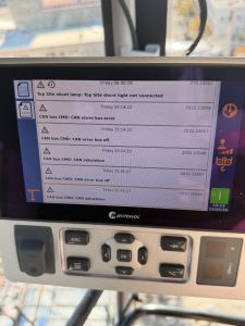
Crane is shutting down during operation, however no fault is displayed and the operation symbol on the LMI bottom right goes from a red circle to flashing green almost immediately. After searching for the fault history (no active faults), found a list of Can Bus faults.
2032.33057 CAN bus CMD: CAN error bus off
2032.33058 CAN bus CMD: CAN alarm bus error
2032.33040 CAN bus CMD: CAN saturation
2032.33058 CAN bus CMD: CAN alarm bus error
2032.33057 CAN bus CMD: CAN error bus off
2032.33040 CAN bus CMD: CAN saturation
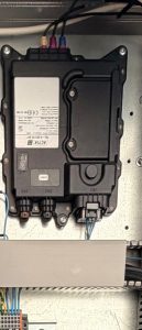
Located on the Can Bus CMD (Command) ‘channel’ is the crane’s modem. Disconnect the top 3 and the bottom large connector. Crane will restart and work
Drive starts up as normal, but when you try to trolley in or out, F0503 fault appears.
Bonfiglioli F0503 is an error code indicating a DC-Link Overcurrent fault
Found input power connector on the bottom of the drive was loose. Pushed it back in completely, and crane is working well.
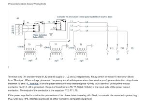
There has been a phase monitoring relay added to Liebherr 81K.1.
It monitors voltage (high and low), frequency (high and low), phase loss and phase order. The display will show all 3 lines of voltage, and relay status. If the relay opens it will shut off crane the same as an e stop, and the message on the remote will show E stop pushed. The display of the relay will flash and an error message will display above the voltage read out.
RL1.PL – Phase loss (one leg is no producing voltage)
RL1.PR – Phase Reverse (Phase order needs changed)
RL1.OV – Over voltage
RL1.UV – Under voltage
RL1.OF – Over frequency
RL1.UF – Under frequency
FLT.INT – Voltage interruption
When look at a component in the electrical cabinet or wire, the number indicates what page in the schematics that the component can be found at. For example, 6U1 is the hoist inverter (VFD) found on page 6. Wire #1503 is found on page 15 and is wire# 03 in a sequence.
S=Hoist (pg 6)
R=Slew (swing) (pg 9)
C=Trolley (pg 12)
KL= Safety validation for the drives
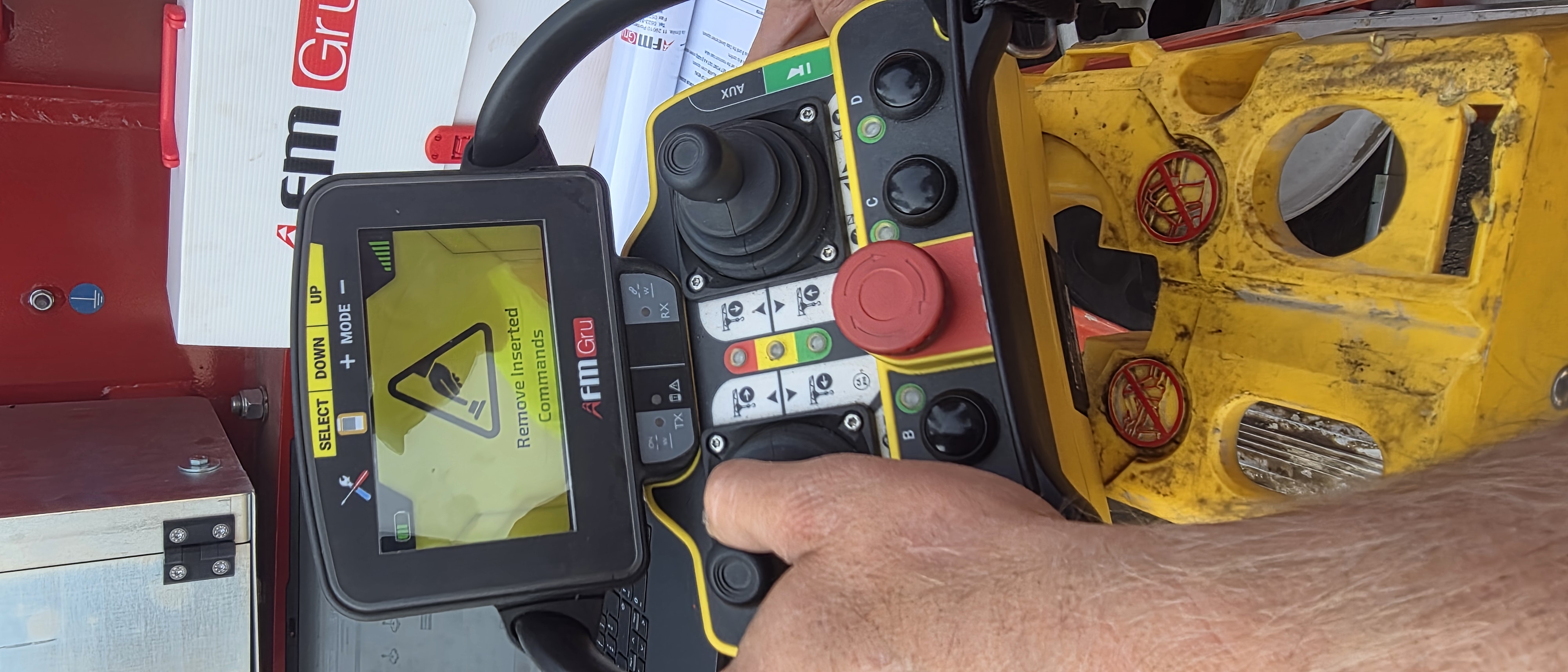
Crane will not start with remote control and display shows “Remove Inserted Commands”
A joystick is out of adjustment and not returning to neutral. Can try and clean connections on the back of joystick, or use app to recalibrate remote.
Crane would start normally, but during start up of drives crane would shut off. Erection screen was inaccurate, because crane would not start up. Faults showed 1-213-001, fault with communication with U213X. U213X had green run and I/O lights. Unplug H5, H6, and H7 (hoist, slew and trolley).
Crane would start and run. Plugged in hoist cable, restarted crane-it worked. Plugged in trolley cable, restarted crane-crane would work. Plugged in slew cable, restarted crane-crane would shut off. Problem could be slew cable, Canopen card in drive or drive itself.
 F=Brake