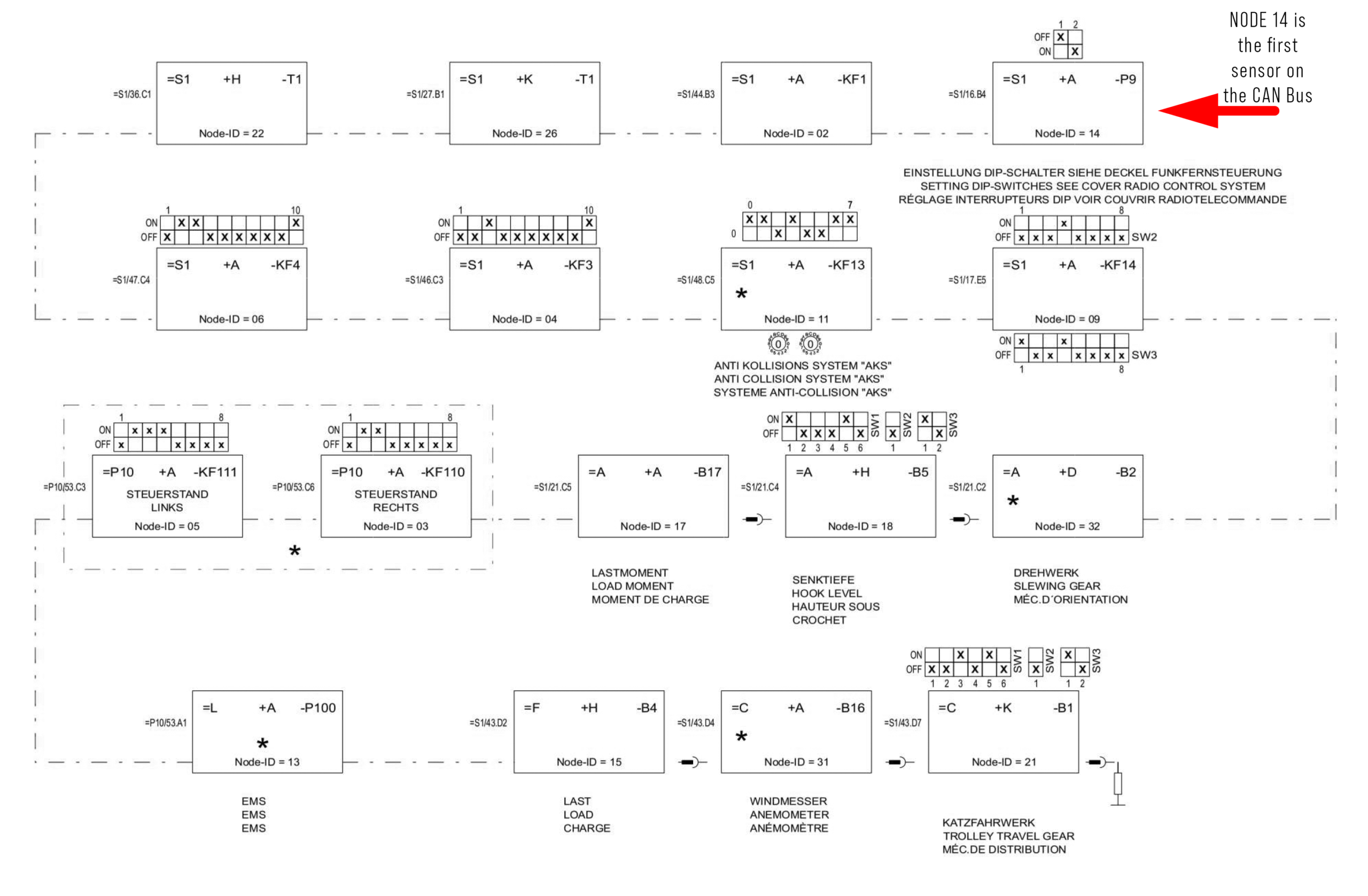
E1502 = CPU (=S1+A-KF1)
E1503 = Control Stand Right (=P1+H-S1)
E1504 = ICN_D64 (=S1+A-KF3)
E1505 = Control Stand Left (=P1+DK-S1)
E1506 = ICN_D32 (Manual Mode 125%) (=S1+A-KF4)
E1509 = Radio remote control (=S1+A-KF14)
E1511 = AKS_unigate (Anti Collision) (=S1+A-KF13)
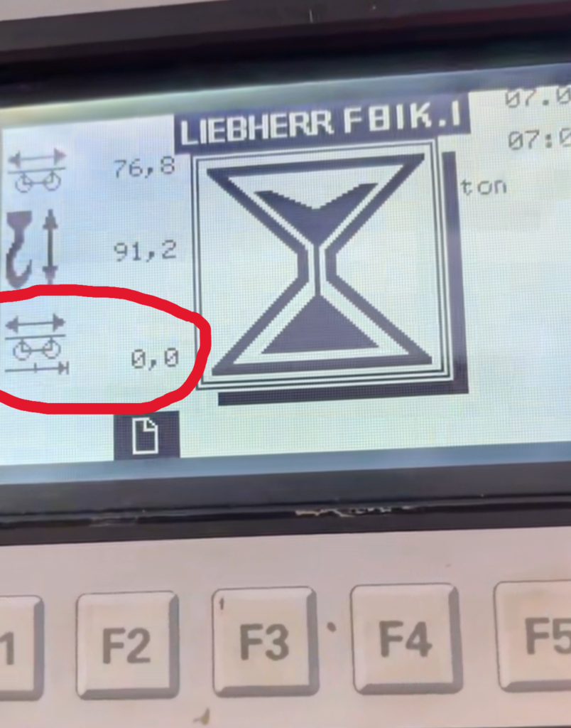
E1513 = EMS Electronic Monitoring System Display (CAB) (=L+A-P0)
E1514 = Display CGM (=S1 +A -P9)
E1515 = Load Measuring Axle (load Pin) (=F+H-B4)
E1517 = Load Moment Sensor (=A+A-B17)
E1518 = Hook height sensor (=A+H-B5)
E1521 = KAW Sensor Trolley sensor (=C+K-B1)
E1522 = WIW-FC Hoist Frequency Drive (=S1+H-T1)
E1526 = KAW-FC Trolley Frequency Drive (=S1+K-T1)
E1531 = Anemometer (=C+K-B1)
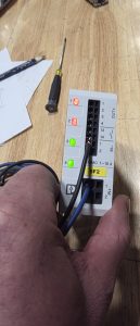
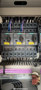
To access CAN Diagnostic Turn off the power to the crane. Open the panel behind receiver and turn the CAN Diagnostic key to the right. Turn the crane back on and wait for the CAN Bus screen to boot.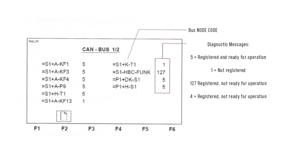
Find the node that is causing the error.
Power off the crane, switch the CAN DIAG back to the left, fix the component that isn’t registering.
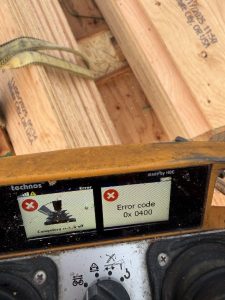
Any Error 1500-1550 indicates the component is no longer on the Bus. The CAN bus is not active for some reason it is possible for the error 1514 to be indicated in the Display as the CPU can no longer communicate with the display via the disrupted bus. Even replacing the CGM Display with not correct the problem!