
81K Crane hoist speed was slow. (no zones, Load plus was turned off) hoist speed was the same as if the micro movement button was pressed. The crane threw code E2647 DC undervoltage
Found the generator idle speed switch was at Low, flipped the switch to High restarted the crane.
Phase Monitoring Relay added
There has been a phase monitoring relay added to Liebherr 81K.1.
It monitors voltage (high and low), frequency (high and low), phase loss and phase order. The display will show all 3 lines of voltage, and relay status. If the relay opens it will shut off crane the same as an e stop, and the message on the remote will show E stop pushed. The display of the relay will flash and an error message will display above the voltage read out.
RL1.PL – Phase loss (one leg is no producing voltage)
RL1.PR – Phase Reverse (Phase order needs changed)
RL1.OV – Over voltage
RL1.UV – Under voltage
RL1.OF – Over frequency
RL1.UF – Under frequency
FLT.INT – Voltage interruption
81K port connection Error – Bad 24V supply and KF2
When the remote shows port connection error it is an indication a Node on the CAN bus is offline. See (CAN BUS CODES) to access the node tree.
In this case the KF2 I/O module was bad.
Found the T7 24Volt power supply light was not on. Internal fuse was blown.
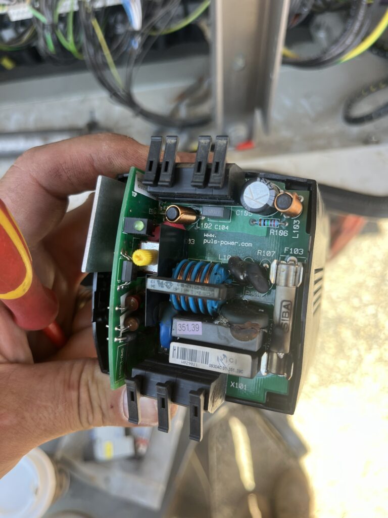
This supply runs the 24V power for the CPU and I/O card. When the power supply was replaced port connection error was still present. Found that cpu was powered and was registering on the node tree but the rest of the nodes beyond the CPU were offline.
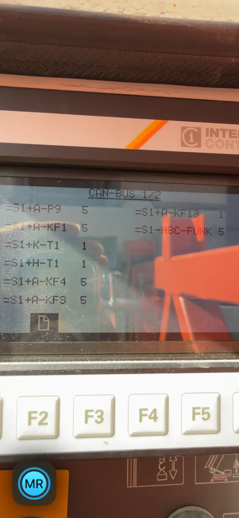
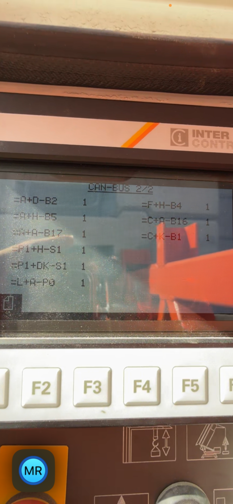
The start command wasn’t being fed to the F10 safety switch. This command is supplied by the CPU and turns on power to the drives. The electrical Schematic lists +A-Q0 as the main start contactor this is actually contactor +A-K001 in the cabinet.
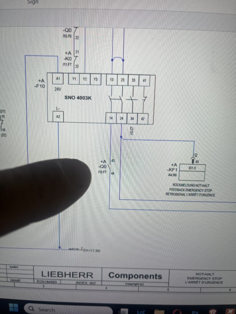
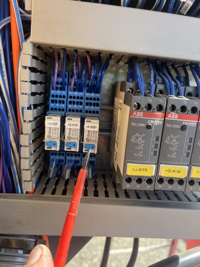
When the contactor was manually activated the drives would fire up. It was determined the KF2 needed replaced to complete the logic sequence . Once replaced, the remoted connected and the crane started.
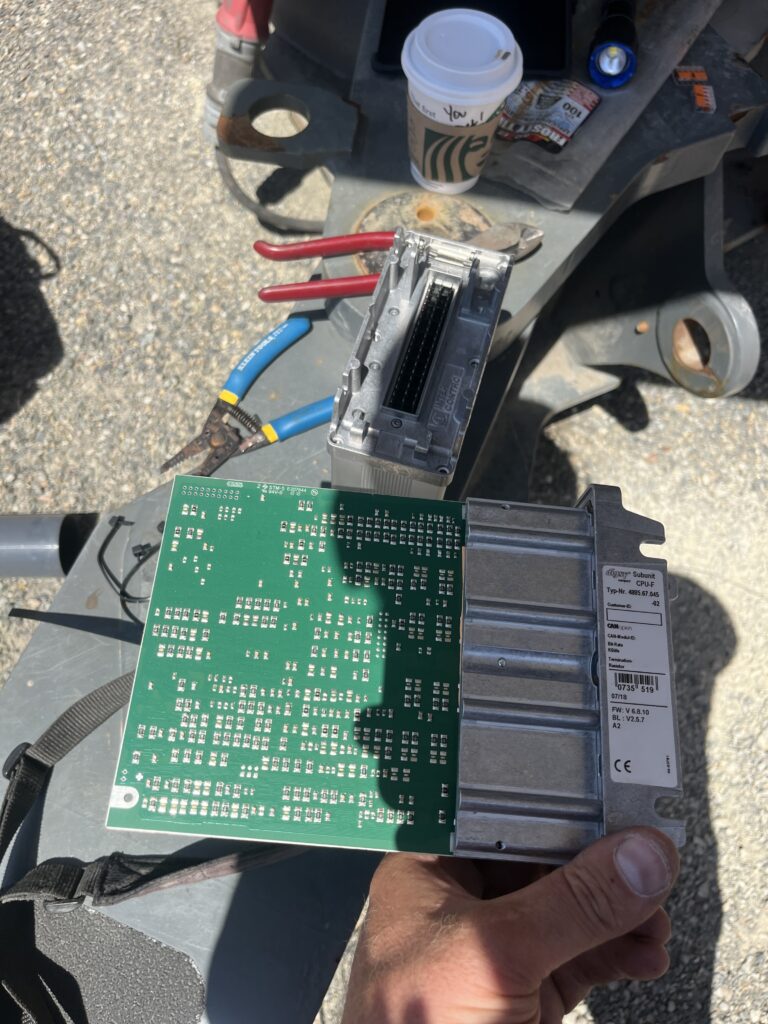
The KF2 is housed along with the KF1. Unbolt the KF1 from the housing (6- T15 Torx bit screws ) and disconnect the ribbon connector to separate the KF1 from the KF2.
81K CAN Bus Codes
E1502 = CPU (=S1+A-KF1)
E1503 = Control Stand Right (=P1+H-S1)
E1504 = ICN_D64 (=S1+A-KF3)
E1505 = Control Stand Left (=P1+DK-S1)
E1506 = ICN_D32 (Manual Mode 125%) (=S1+A-KF4)
E1509 = Radio remote control (=S1+A-KF14)
E1511 = AKS_unigate (Anti Collision) (=S1+A-KF13)
E1513 = EMS Electronic Monitoring System Display (CAB) (=L+A-P0)
E1514 = Display CGM (=S1 +A -P9)
E1515 = Load Measuring Axle (load Pin) (=F+H-B4)
E1517 = Load Moment Sensor (=A+A-B17)
E1518 = Hook height sensor (=A+H-B5)
E1521 = KAW Sensor Trolley sensor (=C+K-B1)
E1522 = WIW-FC Hoist Frequency Drive (=S1+H-T1)
E1526 = KAW-FC Trolley Frequency Drive (=S1+K-T1)
E1531 = Anemometer (=C+K-B1)
To access CAN Diagnostic Turn off the power to the crane. Open the panel behind receiver and turn the CAN Diagnostic key to the right. Turn the crane back on and wait for the CAN Bus screen to boot.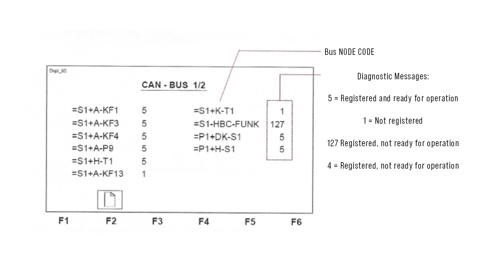
Find the node that is causing the error.
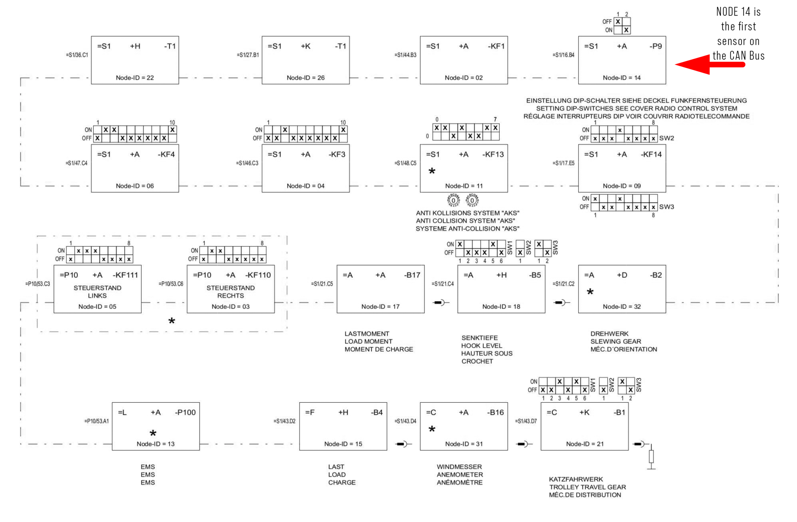
Power off the crane, switch the CAN DIAG back to the left, fix the component that isn’t registering.
Any Error 1500-1550 indicates the component is no longer on the Bus. The CAN bus is not active for some reason it is possible for the error 1514 to be indicated in the Display as the CPU can no longer communicate with the display via the disrupted bus. Even replacing the CGM Display with not correct the problem!
E1514 Code
Operator lost all functions and the remote displayed Port Connection Error .
The electrical panel PLC displayed an hour glass and E1514. Crane would not start.
Any Error 1500-1550 indicates the component is no longer on the Bus. The CAN bus is not active for some reason it is possible for the error 1514 to be indicated in the CGM as the CPU can no longer communicate with the CGM display via the disrupted bus. Even replacing the CGM Display with not correct the problem!
Switched crane to scaling position 1 on the three position key. This would allow the crane to start.
Crane had zero for jib length. The crane has lost jib information and needs to be reconfirmed
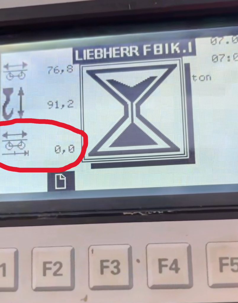
Press F3 for scaling summary. All icons should have a checkmark next to it.
Liebherr Scaling Screenshot
Any icons that have a “X” next to it need to be reconfirmed. F1 to previous screen, and F2 to confirm each icon. Must confirm the OK at the end as well.
Liebherr 81K.1 shutdown and won’t restart
The crane lost eception with the remote and shutoff. The operator tried to restart and it would not restart. The operator took a picture of the following code.
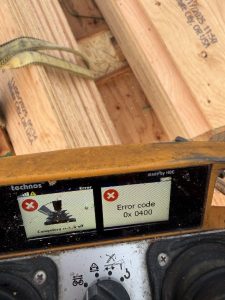
The code 0x 0400 means the remote is asked to start (restart), but there is a function being applied at the same time. The operator was in mid-swing when it lost reception and the operator did not release the joystick when he tried to restart. The picture shows this.
Liebherr 81K.1 won’t swing
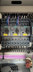
Customer called and crane won’t swing. Crane will hoist and trolley, but no swing. Error code “E 705”. Slowing gear safety device. Thaddeus was able to FaceTime with customer and found slew drive circuit breaker was tripped.
Crane load indication accuracy
1917.46(a)(1)(ii)
The accuracy of the load indicating device, weight-moment device, or overload protection device shall be such that any indicated load (or limit), including the sum of actual weight hoisted and additional equipment or “add ons” such as slings, sensors, blocks, etc., is within the range between 95 percent (5 percent underload) and 110 percent (10 percent overload) of the actual true total load. Such accuracy shall be required over the range of daily operating variables reasonably anticipated under the conditions of use.
Liebherr Jib pin
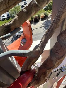 Need to make sure you pull down on the cable that is attached to the jib release pin while folding up jib. It can get stuck and not slide properly and will bend plate. Which won’t latch properly.
Liebherr auxiliary motor went down.
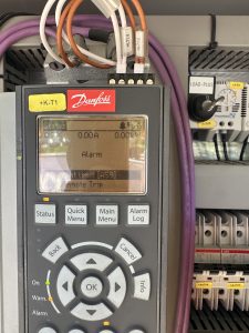
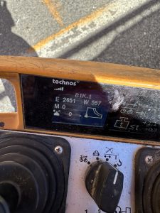 When trying to fold the jib out it would stop and throw an error on the remote E 2651. Which means Torque limit motor reached. When using the motor it was putting out 11 to 15 amps before kicking out. A good motor at full speed puts out 5to 8 amps while working properly. You can find your amp pull right on the drive +k-T1. Replaced aux motor and was drawing 7 amps