When trying to start crane, the PLC and the load sensor were not turning on. The top light on this device was flashing red.
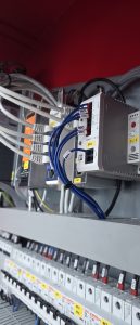
This is an electronic circuit break. Found the short, and corrected. The red light can be pushed to reset.
Rocky Mountain Crane Service Logs
When trying to start crane, the PLC and the load sensor were not turning on. The top light on this device was flashing red.
This is an electronic circuit break. Found the short, and corrected. The red light can be pushed to reset.
1917.46(a)(1)(ii)
The accuracy of the load indicating device, weight-moment device, or overload protection device shall be such that any indicated load (or limit), including the sum of actual weight hoisted and additional equipment or “add ons” such as slings, sensors, blocks, etc., is within the range between 95 percent (5 percent underload) and 110 percent (10 percent overload) of the actual true total load. Such accuracy shall be required over the range of daily operating variables reasonably anticipated under the conditions of use.
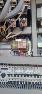
Rundown of relay to contactor logic

Contactor 34K1 controls valve bank coils.
Y1 Mast down
Y2 Mast up
Y3 Jib up
Y4 Jib down
Relay bank

36K1-5 relays
36K1 Mast down (34K1-Y1)
36K2 Mast up (34K1-Y2)
36K3 Jib up (34K1-Y3)
36K4 Jib down (34K1-Y4)
36K5 Control relay (supply)
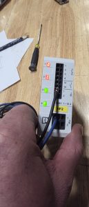
Tried to erect 1589 and the jib would not raise. Checked hydraulic pump, and it was building pressure, but the coil to open the valve bank was not being activated.
Contactor was switching to open, but the control relay for the valve was bad.
Light would turn on the face of the relay, but would not actually switch. The orange screw could be turned to manually make the switch and the jib would go up. Replace relay.
This is only for the Upper and Lower hoist limits and the Inner and Outer Trolley Limits
—– Limit calibration —–
With machine in work,
press the radio control buttons A and D simultaneously for at least 5s until the radio control buzzer sounds.
At this point the machine goes into calibration mode and the radio control screen changes showing the current maximum and minimum limits.
It is possible to move the lifting and trolley axes WITHOUT LIMITATION to bring them manually to the maximum and minimum positions.
Once the limit position has been reached, by keeping the corresponding button pressed for at least 3s, the quota (minimum or maximum) will be fixed to the current position of the axis
and to the value displayed by radio control.
The keys are assigned as follows:
– key A for minimum lifting limit (LOWER LIMIT CLOSEST TO GROUD)
– key B for maximum lifting limit (UPPER LIMIT CLOSEST TO JIB)
– C key for minimum cart limit (INNER TROLLEY LIMIT)
– D key for maximum cart limit (OUTER TROLLEY LIMIT)
The LEDs positioned above the keys indicate whether the limits calibration has been carried out (LED on steadily) or not (LED off), respectively at the minimum and maximum lifting and trolley levels.
——————-