Crane stopped working one morning when the operator doing warm up. Start the crane up and all the drives fire up but trolley immediately goes to FST.
We plugged in the handheld and crane works fine.
Got this from Tomas and he said you should try this if the crane is acting funny and you can’t get figure what it is.
Dusty,
Try this.
Hello Tomas,
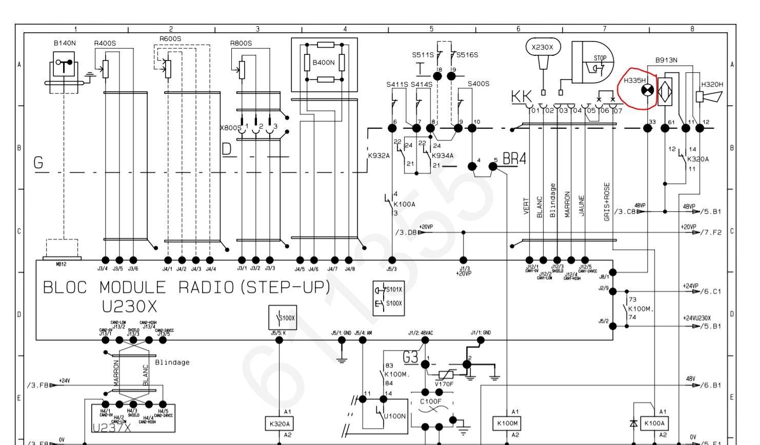
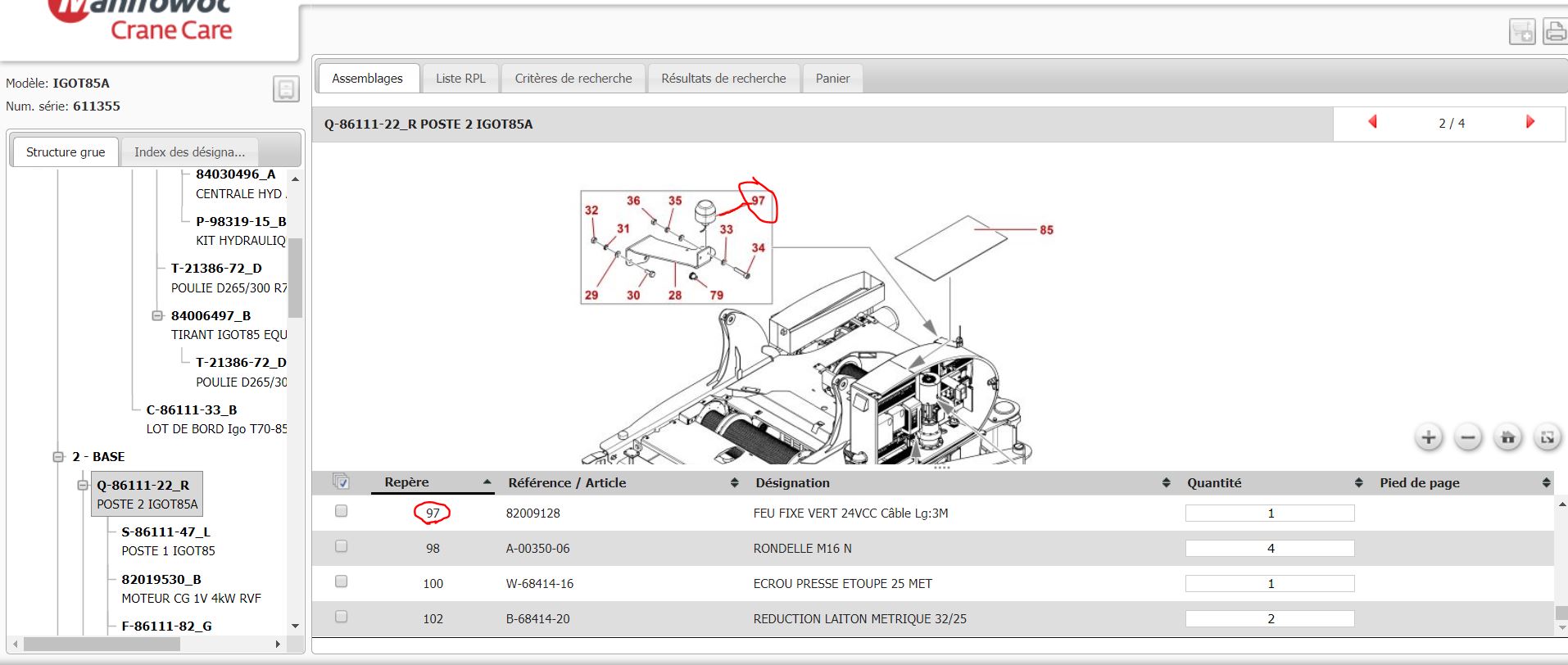
We think you have an issue with H335H (green light). This light is connecting on Terminal G-33 (only with remote control ).
Try to disconnect it and work with remote control. Please find in attachment the light part number.
Best regards