Press and hold the X button for 10 – 15 seconds. Warning light will disappear and interval will reset.
AMCS on Igo T85A will not trolley
The AMCS system did not record inner and outer limits for the trolley sensor.
Go to the sensor screen, and click on the “Gear” icon next to the trolley sensor
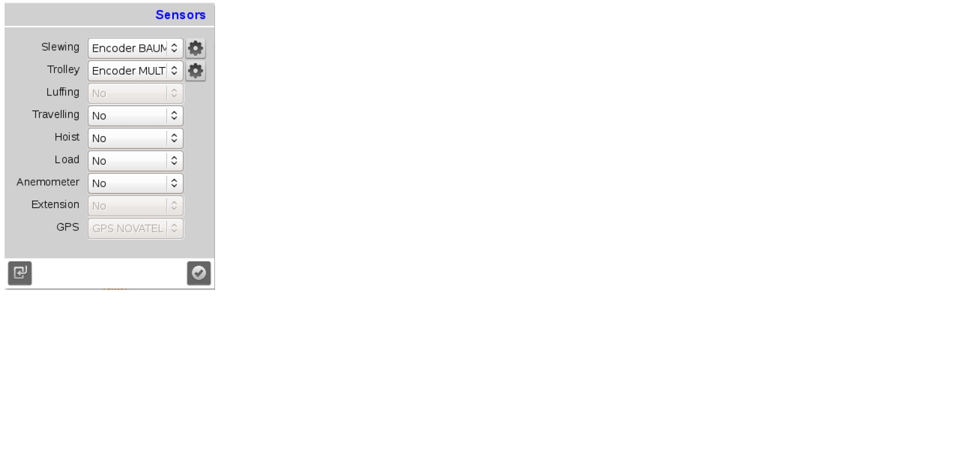
The top line of the should show the current position of the trolley.
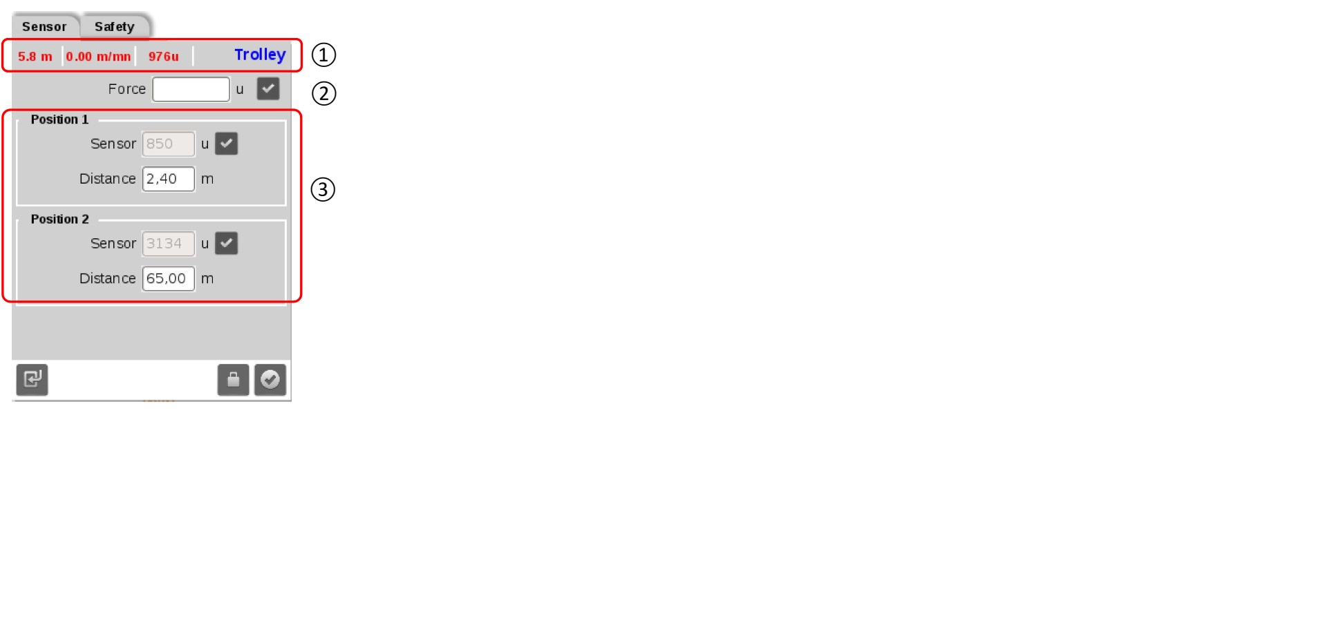
Although you can set position 1 or 2 first, start with position 2 (the outer limit), so you can trolley back in and set the inner limit (position 1). Once you position the trolley at the outer limit, verify the distance and sensor value and click the checkmark box. Repeat for position 1 at the inner trolley limit
Crane lost slew function AFE1 Code on slew drive
Crane lost slew function. AFE1 displayed permanently on screen. If cleared, drive would shut down. 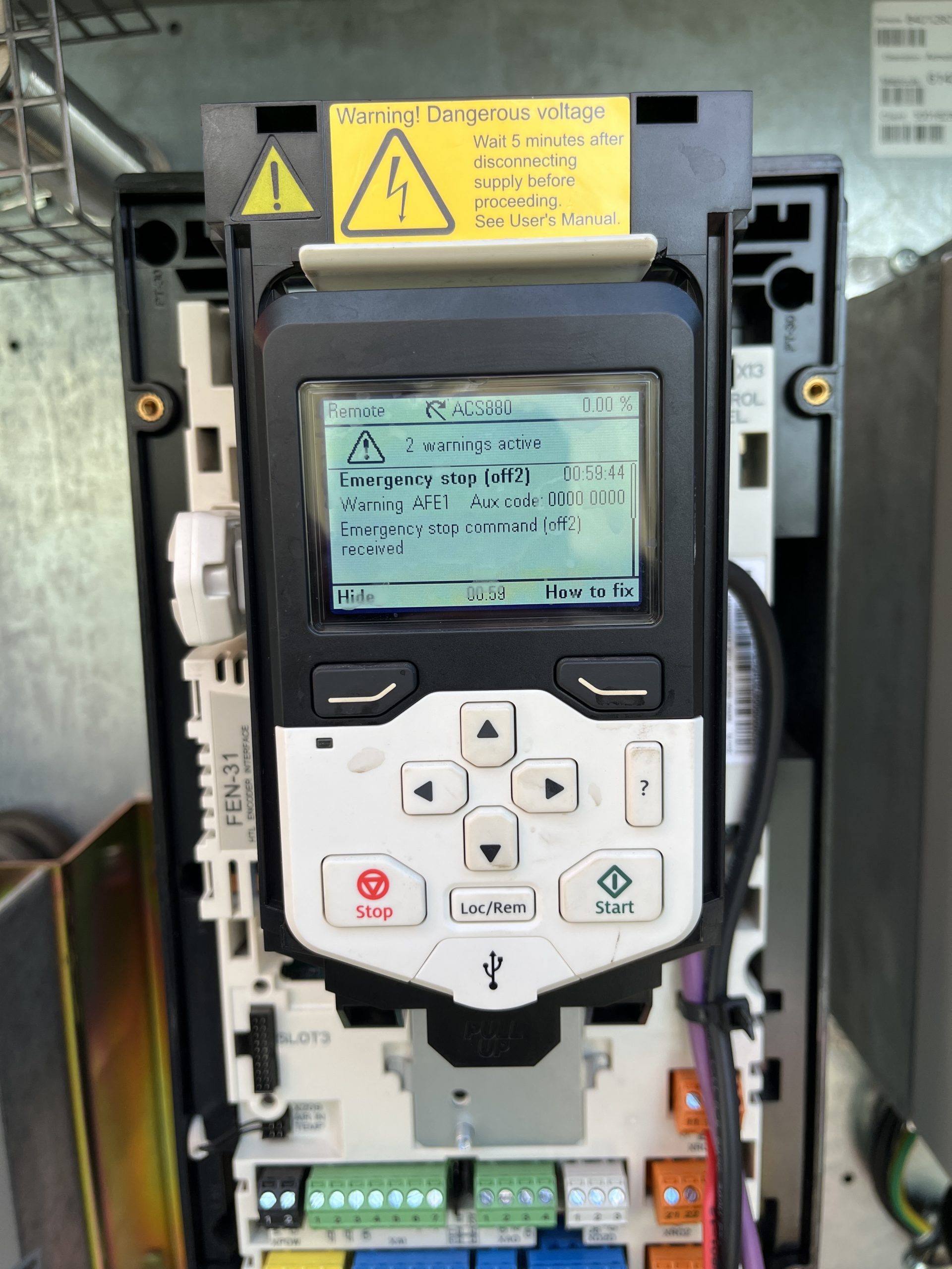 Checked voltage at XD24-2 24V connection on slew drive. Voltage was present but not 24V. Checked XD24-1 connection at slew drive Voltage was present but not 24V. Removed the XD24-2 wire are rechecked and voltage was 24V. Determined K600M Contactor was faulty.
 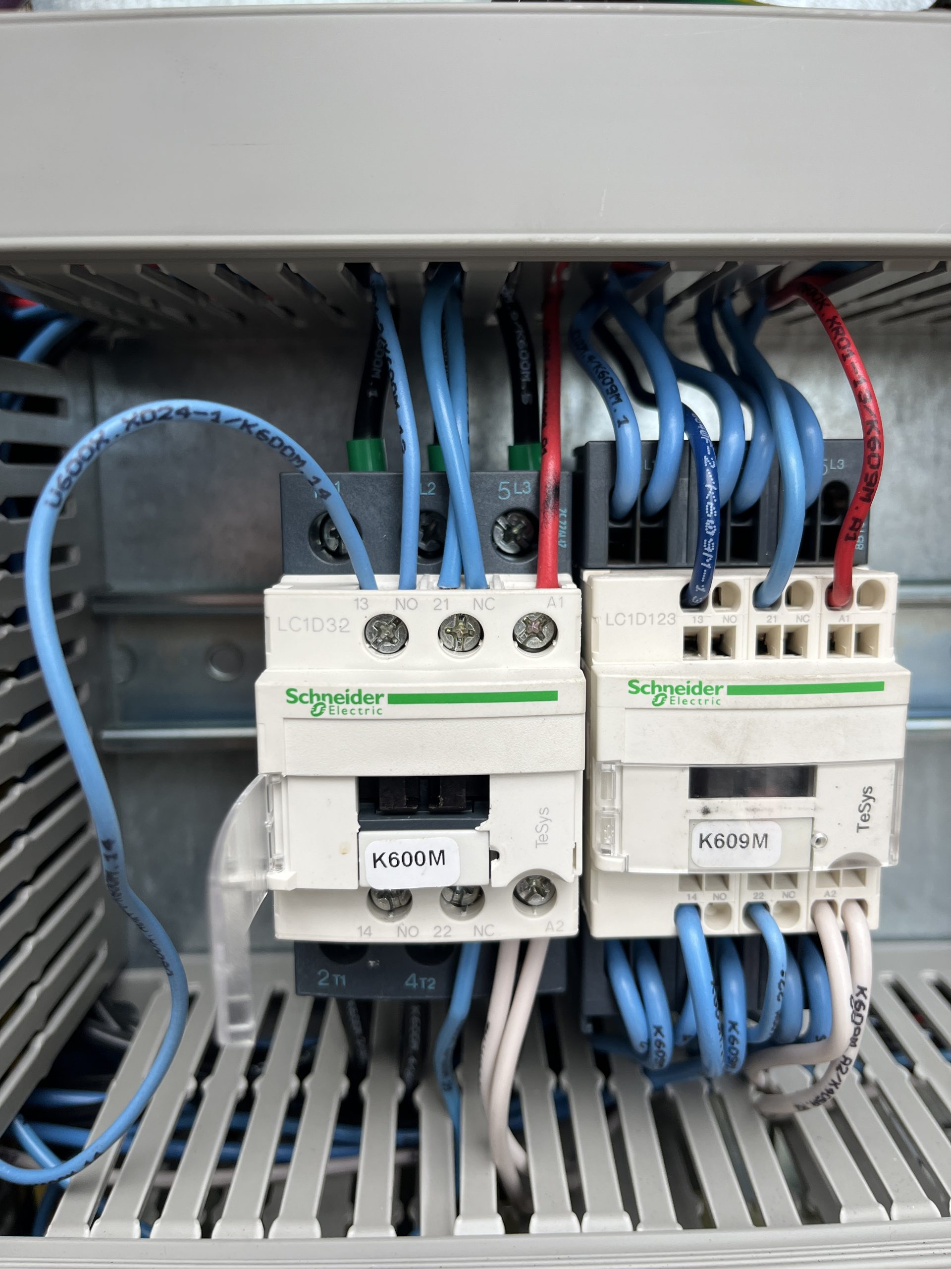 If a new contactor isn’t available. K466M
 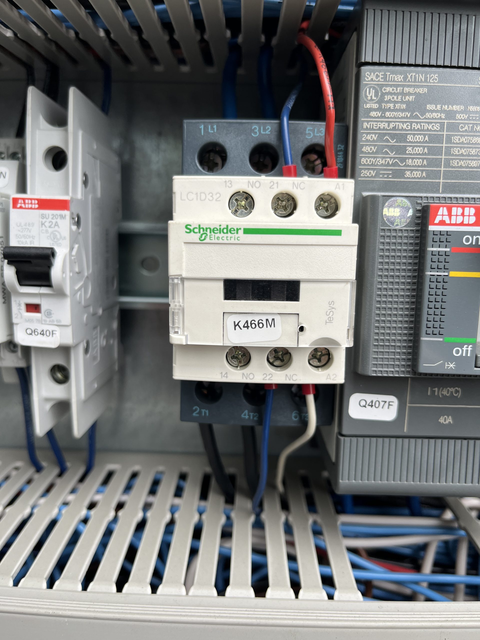 (motor preheat contactor) is the same and doesn’t use the 13/14 connections. This a great contactor to use to get the crane up and running.
Removing outer jib, 104ft IgoT85
After you bring the crane into maintenance mode and get it in the position to start taking the Hydraulic cylinder, jib attachments, and jib off. The operator manual disassembly instructions do not match the actual process to remove the outer jib.
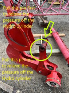
With the pictures above the picture from the manual tells you to pull this pin to get the cylinder off. Which there is to much pressure on the cylinder to get that pin out with out possibly bending the Jib on the crane. When you get to this step of taking the Hydraulic Cylinder off you will want to revert to the edited picture above and pull that pin first.
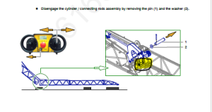
The operator manual disassembly instructions do not match the actual process to remove the outer jib. When removing the outer connecting rod/hydraulic assembly, there is no need to remove the pulley pin and roller assembly as detailed in this step.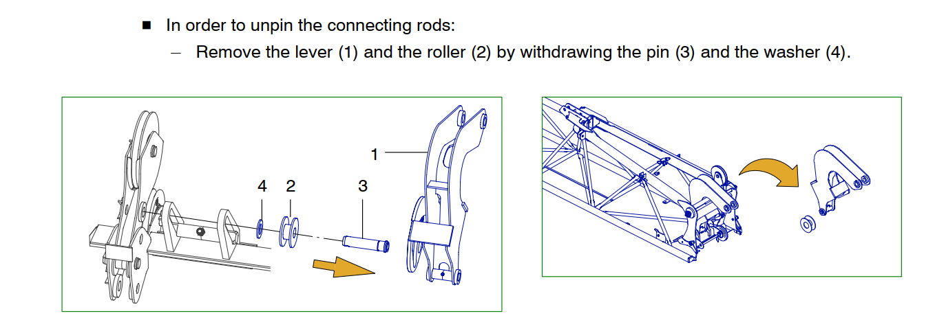
The connecting rod (4)(image below) pivots on a special pin with a through bolt. To remove the connecting rod (4) Remove the through bolt, slide out of the connecting rod pin (4) The sheave assembly that is detailed in the image below (1) is separate and will unpin without any interference from the Connecting rod (4)
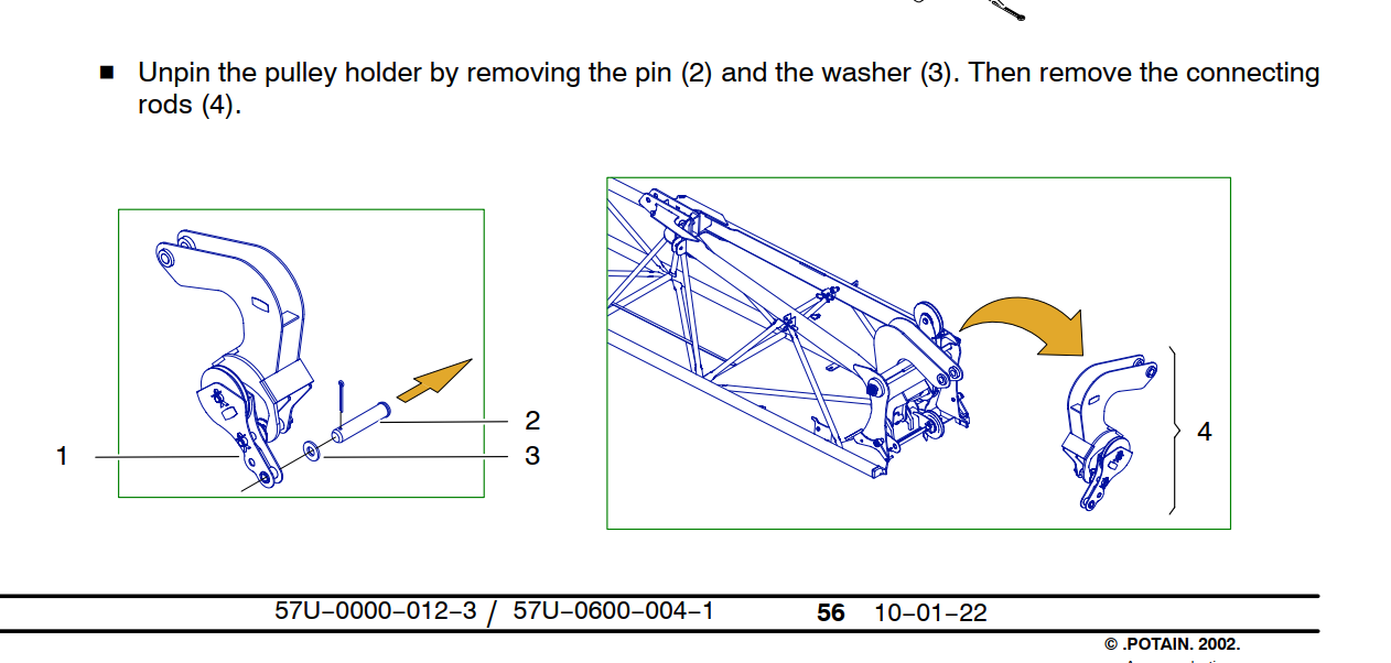
The connecting rod pin fits into a slotted rail, the pin needs to be at the bottom of the rail and turned 1/4 turn to be removed. (Note the trolley cable sheave is installed and pined into place. The pin required to pin the sheave is the same pin used to hold the pulley holder (1) in place. There is some paint in the I.D. of the holes, it is recommended to install the pin first with anti-seize to help drive out the paint before installing the sheave. )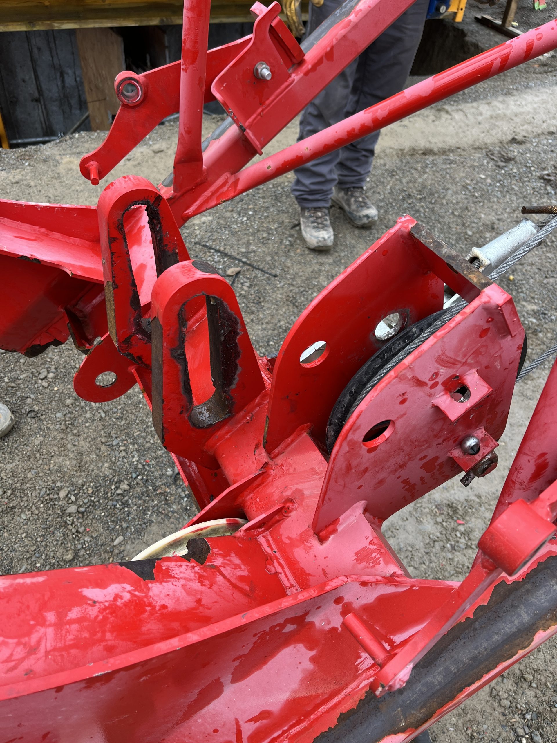
The connecting rod assembly can be removed without completely disassembling the assembly as detailed in the instructions.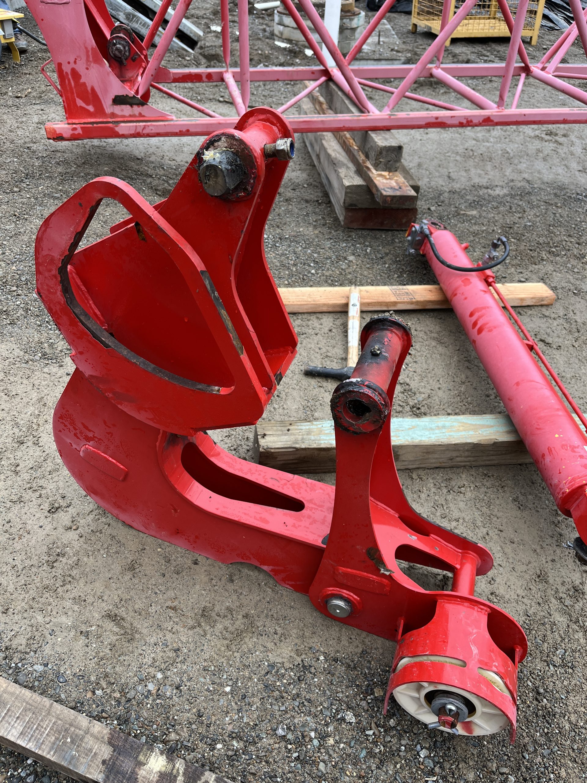
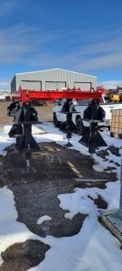
600 Series Anchors
On P62US (same as P62B) anchors, tapered pins (longer of the 2 pins, 60mm and 59mm) go through spigot and template (tower). These will be the bottom tower pins. Straight pins (59mm) go through anchor and spigot.
Measure the pins and fishplates )spigots) to be sure. Also check for which holes to use on the template.
AMCs not working
trolley on display had a ??? Which made AMCs not work. Wires were pulled out of 3 and 5 on the analog on processor
Removing or Install Contactors to DIN rail
For Schneider Electric (Telemechanique) contactors, press down on the top of the contactor and pull the bottom off the rail, then lift up off the rail. For installation, slide the top over the rail, and press down to snap the bottom on and release.
Please see video:
Service Guide for T85 Slew motor
Also is saved in Dropbox under T85
Swing motor
Swing motor parts diagram is also attached
SERVICE+GUIDE-GS-2022-001-2 (1)
Slew Drive Faults with code 7510 at Start Up
This is similar to the service post found here:
However in this instance, isolating the Slew Drive by disconnecting hoist drive and trolley drive from the CAN system did not help. Checked for 60ohms on the CAN Hi and CAN Lo . This should confirm that the jumpers in both of the erection jumper plugs are there and correct. Found CANOpen card was not operating correctly.
Unplugged and plugged back in the CANOpen card and plug. Unplug and replug the memory stick back in. No change. Replace memory stick and drive came back up on line.
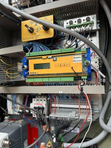
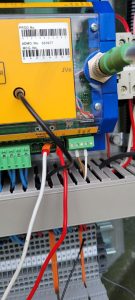
U230X Processor not powering on.
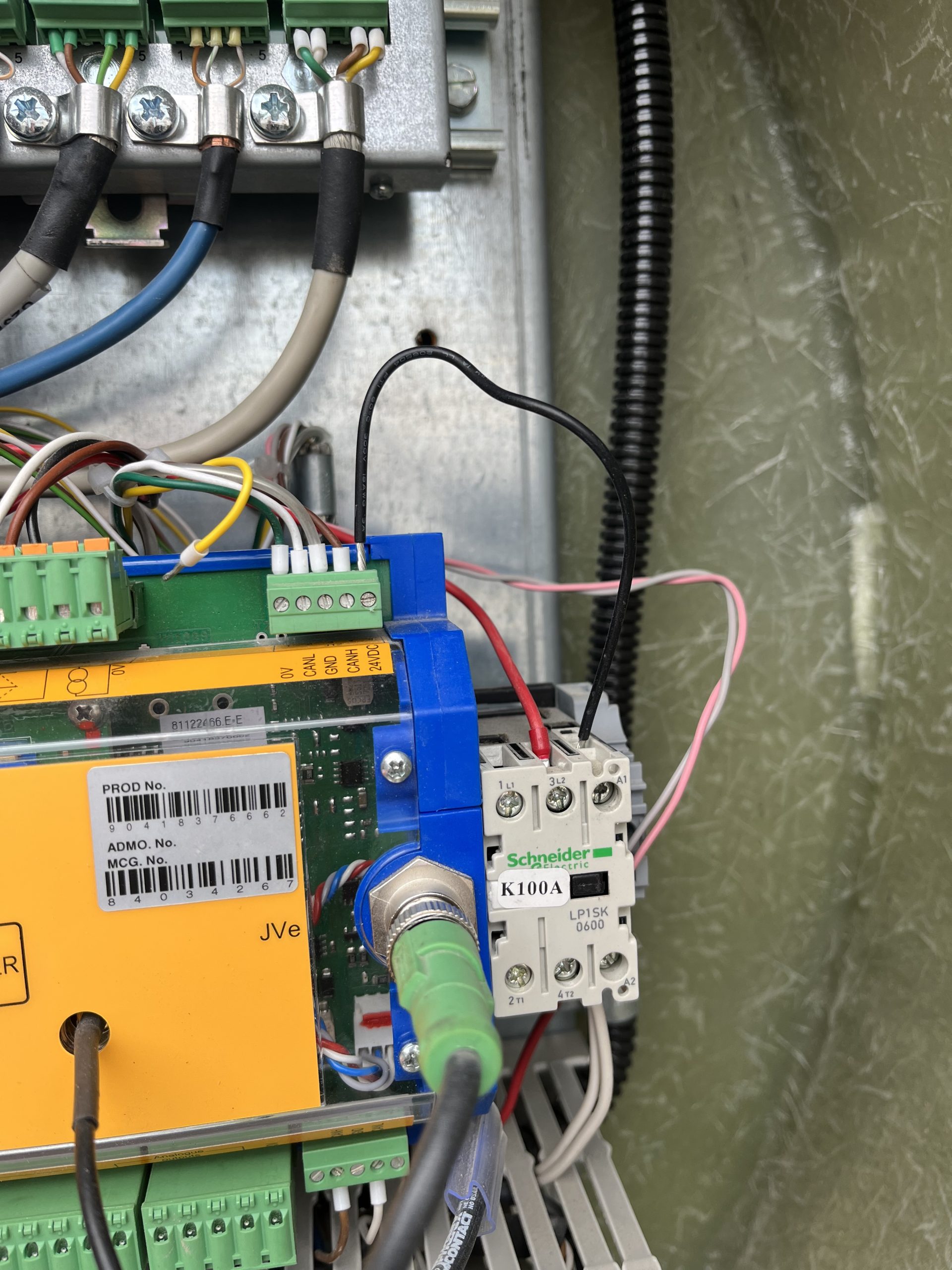
Customer complaint was that the crane would not connect to the remote. It was found the U230X Processor display wasn’t on, but the light shining on the processor was on. A voltage reading of 50V was taken at the J1/2 and continuity reading was taken at J1/1. It was noted that K100A wasn’t energized. A voltage reading at J12/5 was taken and found a reading of 0Volts
The U230X has an internal fail safe that if there is something wrong with the start sequence it will not power on. In this instance all outgoing connections were removed until only the J1 Connection was left connected to the processor. The crane was powered on and the processor powered up showing information on the display. One by one each J connection was added until the processor would not power on. It was found that the J12 connection was the offending connection. The 24V connection at J12/5 was removed at the processor and and the crane processor powered on. The crane was once again powered down and a continuity reading was taken from the J12/5 wire to each J12 connection. It was found that the J12/5 was making contact to the J12/1, J12/3, and chassis ground. The customer inspected the KK plug for a connection error and it was found the wiring to the KK plug was compromised internally. As a temporary fix to allow the operator to continue to work a jumper wire was ran from J12/5 to the A1 connection on the K100A. The crane operates as it should. Replacement of the KK plug wiring should be taken in this instance.