
Serial number 602585
Top slew minimum adjustment of moment sensor

All Top slew CCS machines
Don’t worry about the measurements, but make sure the mA’s are dead on.
Hoisting Problem on MDT
Re routed the can bus cable and got it away from all the high voltage incoming cables, brake chopper cable etc
Fault has cleared it self . Crane is picking fine
Going to monitor for a little while longer
It is the 3 wire plug that goes into the faceplate of the drive.
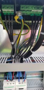
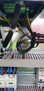
Before/After
Checking Slew bolt Torque
Potain 27148 T85 Electrical Diagram
Potain 27148 T85 Change Rope Reeving to SM1
Threshold for Load on T85
Make sure to be aware of the different password you must enter to get into these settings.
We went as low as we could in California, which was 90%
Layout for Outriggers
T85 and HUP 40/30
14’8″ center to center 20’8 7/8″ Diagonal
HUP 32/27
13′ Center to Center 18′ 4 5/8″ Diagonal
Liebherr 81k.1
14′ 9″ Center to Center 20′ 10 5/16″ Diagonal
HDT 80 – Comm Error
Justen from CLS called and said the remote was showing Comm Error. Talking with Tomas, it is the data being sent from receiver to the remote (transmitter) for the display. Check the connection at the receiver with the red antenna for loose or corrosion at the connection. Also, check inside the remote there is an antenna that can come loose or fall off. If all looks good, need to replace both receiver and transmitter.
Field Testing 3 Phase Electrical Motors
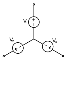
Pictured is a standard “Wye” connection. First test is the “megger” test which measures resistance to ground. Should be 800-900 Mega ohms (MΩ) resistance (our tester reads up to 500 Mega ohms)
- Connect megger to V1 and to Ground. Run test, should exceed 500MΩ
- Connect megger to V2 and to Ground. Run test, should exceed 500MΩ
- Connect megger to V3 and to Ground. Run test, should exceed 500MΩ
In theory they all share the neutral in the middle, and testing only 1 leg should be sufficient, but this isolates each leg
Next test is a resistance of the windings for each leg
- Resitance test should be between V1 → V2, V2 → V3, V1 → V3 and all values should be the same. Corrosion on terminal connections may result in different values, but should all be very close (within .5 Ω to .05 Ω)
Final test would be current draw on each leg, but would require an amperage clamp and ability to run motor continuously.
- I of V1 = I of V2 = I of V3 “should” all be equal