81K port connection Error – Bad 24V supply and KF2

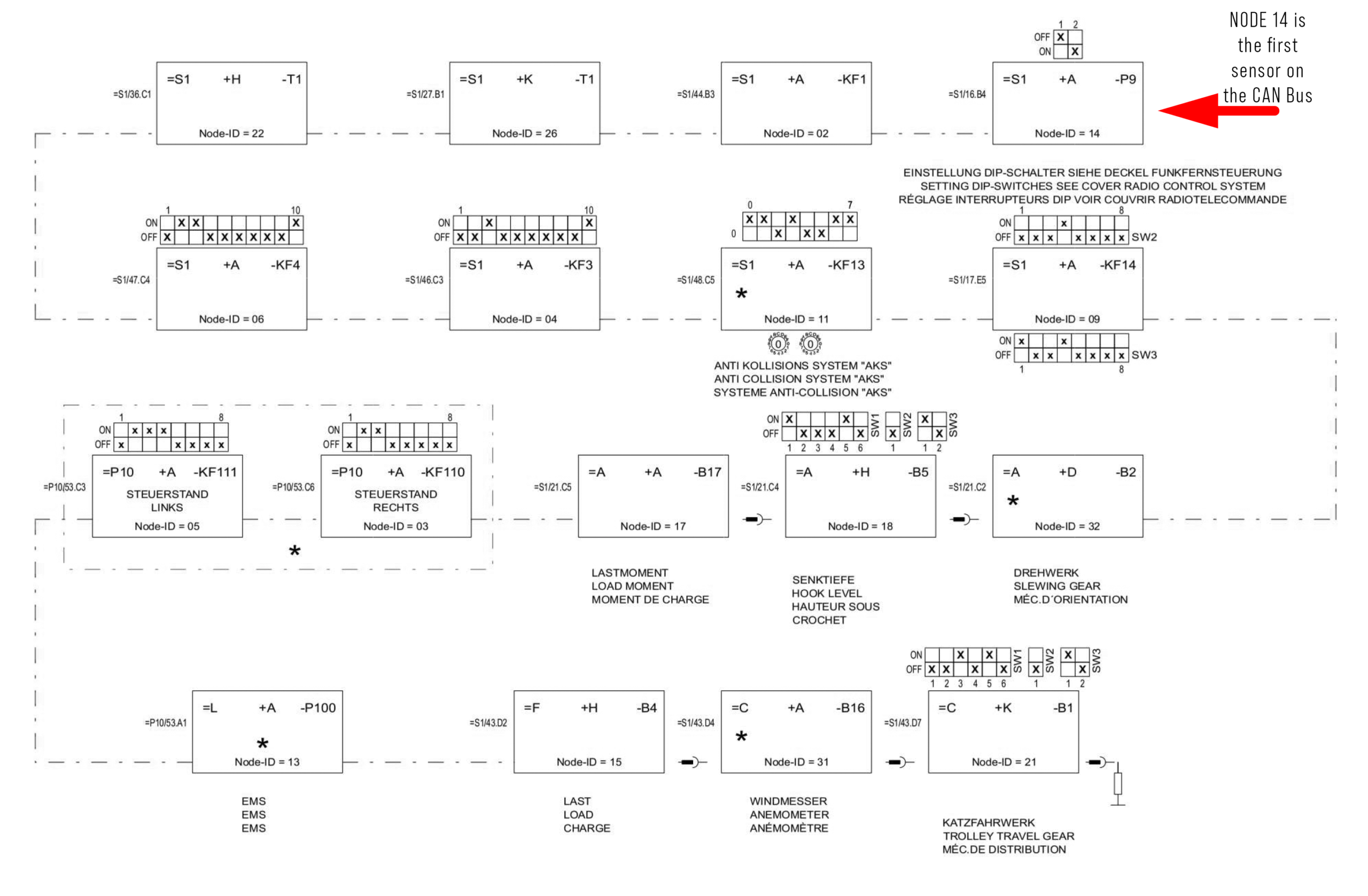
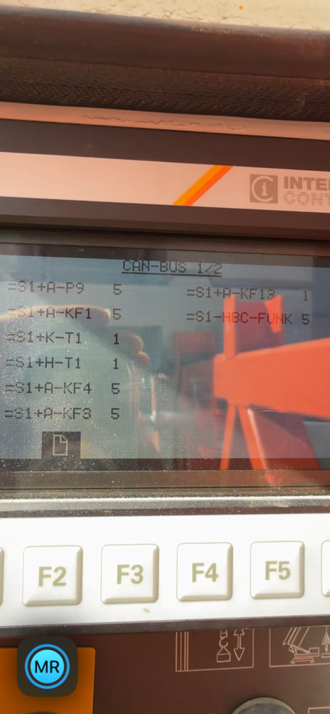
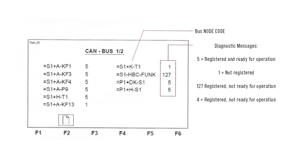
When the remote shows port connection error it is an indication a Node on the CAN bus is offline.  See (CAN BUS CODES) to access the node tree. 

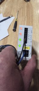
In this case the KF2 I/O module was bad.

Found the T7 24Volt power supply light was not on. Internal  fuse was blown.
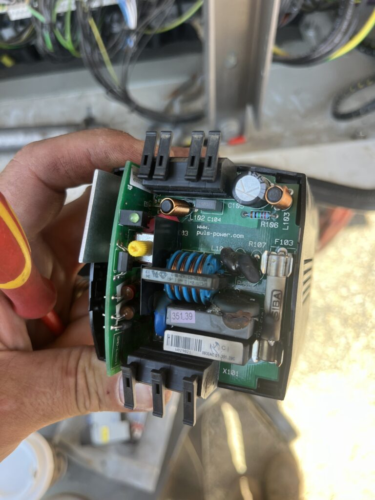
This supply runs the 24V power for the CPU and I/O card.  When the power supply was replaced port connection error was still present. Found that cpu was powered and was registering on the node tree but the rest of the nodes beyond the CPU were offline. 
The start command wasn’t being fed to the F10 safety switch. This command is supplied by the CPU and turns on power to the drives. The electrical Schematic lists +A-Q0 as the main start contactor this is actually contactor +A-K001 in the cabinet.
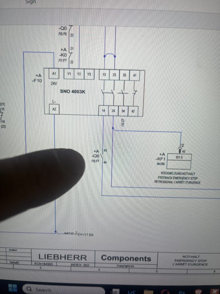
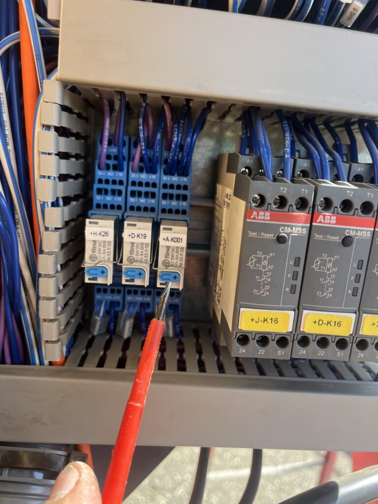
When the contactor was manually activated the drives would fire up. It was determined the KF2 needed replaced to complete the logic sequence . Once replaced, the remoted connected and the crane started.  
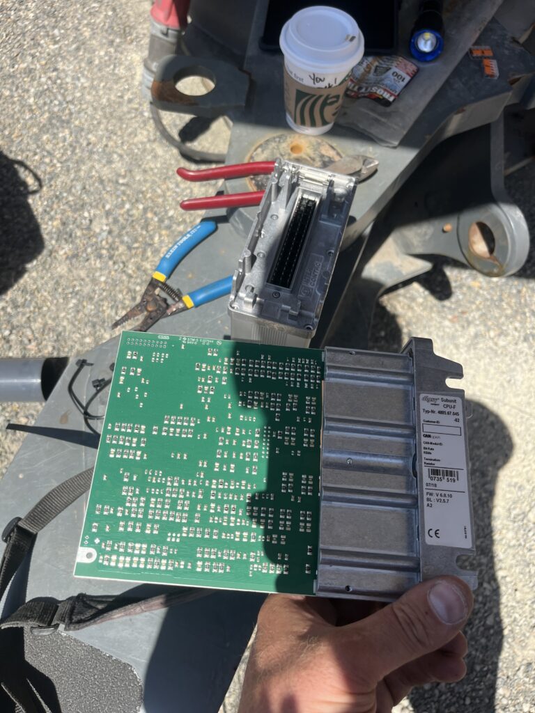
The KF2 is housed along with the KF1. Unbolt the KF1 from the housing  (6- T15 Torx bit screws ) and disconnect the ribbon connector to separate the KF1 from the KF2.
 

Teach In for New Version of Hup

To begin teach in, you must first choose the target (H0, H1, 10, 20) and then you can set the radius.

You must also set the minimum AND the maximum radius.

To set “0” load, you must lower the hook past where the hoist rope is in the middle of the drum; and then you hoist up to where the hoist rope is in the middle of the drum.

You are also required to set the “known” load.

If you do not set the 3 dead turns, an envelope will show in the upper left corner and the message will be that the 3 dead turns has not been set.

The newest version of the CCS manual is here

CCS V1.13-ENU

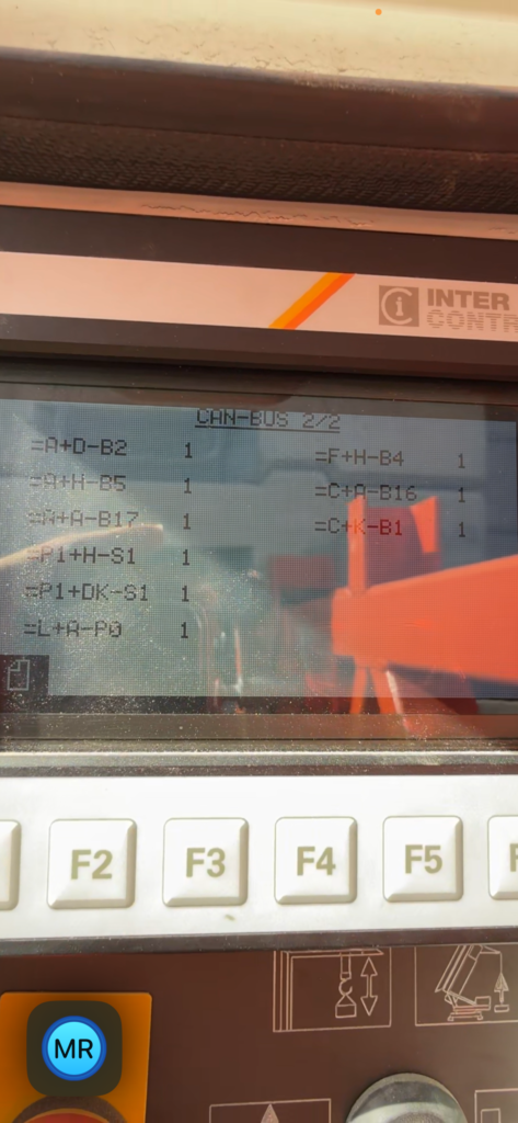
81K CAN Bus Codes

E1502 = CPU (=S1+A-KF1)

E1503 = Control Stand Right (=P1+H-S1)

E1504 = ICN_D64 (=S1+A-KF3)

E1505 = Control Stand Left (=P1+DK-S1)

E1506 = ICN_D32 (Manual Mode 125%) (=S1+A-KF4)

E1509 = Radio remote control (=S1+A-KF14)

E1511 = AKS_unigate (Anti Collision) (=S1+A-KF13)

E1513 = EMS Electronic Monitoring System Display (CAB) (=L+A-P0)

E1514 = Display CGM  (=S1 +A -P9)

E1515 = Load Measuring Axle (load Pin) (=F+H-B4)

E1517 = Load Moment Sensor (=A+A-B17)

E1518 = Hook height sensor (=A+H-B5)

E1521 = KAW Sensor Trolley sensor (=C+K-B1)

E1522 = WIW-FC Hoist Frequency Drive (=S1+H-T1)

E1526 = KAW-FC Trolley Frequency Drive (=S1+K-T1)

E1531 = Anemometer (=C+K-B1)

To access CAN Diagnostic  Turn off the power to the crane. Open the panel behind receiver and turn the CAN Diagnostic key to the right. Turn the crane back on and wait for the CAN Bus screen to boot.

Find the node that is causing the error.

Power off the crane, switch the CAN DIAG back to the left, fix the component that isn’t registering.

Any Error 1500-1550 indicates the component is no longer on the Bus.  The CAN bus is not active for some reason it is possible for the error 1514 to be indicated in the Display as the CPU can no longer communicate with the display via the disrupted bus. Even replacing the CGM Display with not correct the problem!

E1514 Code

Operator lost all functions and the remote displayed Port Connection Error .
The electrical panel PLC displayed an hour glass and E1514. Crane would not start.

Any Error 1500-1550 indicates the component is no longer on the Bus.  The CAN bus is not active for some reason it is possible for the error 1514 to be indicated in the CGM as the CPU can no longer communicate with the CGM display via the disrupted bus. Even replacing the CGM Display with not correct the problem!
Switched crane to scaling position 1 on the three position key. This would allow the crane to start.
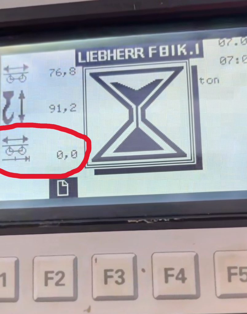
Crane had zero for jib length. The crane has lost jib information and needs to be reconfirmed


Press F3 for scaling summary. All icons should have a checkmark next to it.

Liebherr Scaling Screenshot

Any icons that have a “X” next to it need to be reconfirmed. F1 to previous screen, and F2 to confirm each icon. Must confirm the OK at the end as well.

FM Gru won’t start

When trying to start crane, the PLC and the load sensor were not turning on.  The top light on this device was flashing red.

This is an electronic circuit break.  Found the short, and corrected.  The red light can be pushed to reset.


Liebherr 81K.1 shutdown and won’t restart

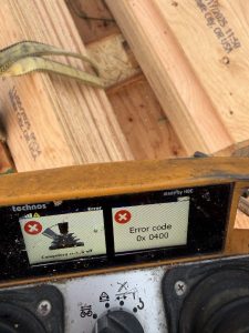
The crane lost eception with the remote and shutoff.  The operator tried to restart and it would not restart.  The operator took a picture of the following code.

The code 0x 0400 means the remote is asked to start (restart), but there is a function being applied at the same time.  The operator was in mid-swing when it lost reception and the operator did not release the joystick when he tried to restart.  The picture shows this.

Liebherr 81K.1 won’t swing

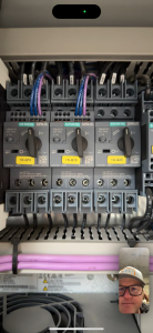
Customer called and crane won’t swing.   Crane will hoist and trolley, but no swing.  Error code “E 705”.  Slowing gear safety device.  Thaddeus was able to FaceTime with customer and found slew drive circuit breaker was tripped.