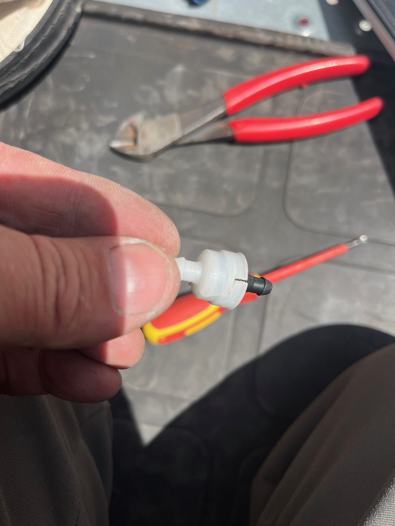
Jumper 2 wires together
Rocky Mountain Crane Service Logs
Jumper 2 wires together
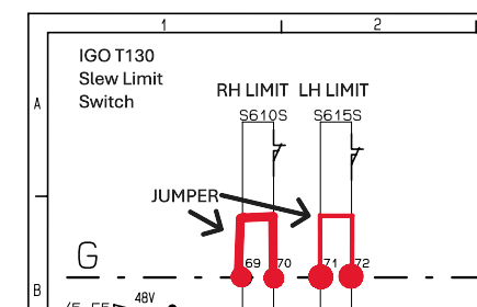
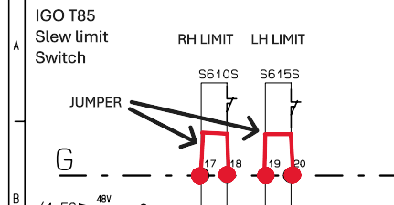
This is the wiring that needs to be jumped in order for the operator to untwist the power cords
Hup had zoning and slew encoders turned on. Encoders would pair, Zero slew angle would accept and zones worked after being set. Normal operation would resume, but the crane would not slew after being shut down at the base (CCT/SCM computers powered off) and restarted after 10 minutes. Scrolling through the menu zero angle wasn’t present. Operator reset zero angle and slew movement was regained until crane was powered off at the base.
1)Turn off Slewing encoder option, This will tell the CCT to not look at the encoder, the crane regained slew.
2) Check slewing encoders for faults. In this case, the main slewing encoder would flash a single red light.
3) replace slewing encoders and pair
4) turn on slewing encoder option
5)Set zero angle and zones
Hoist Drive was saying it was RDY but had no functions on hoist. Erection aid was saying >30 dregrees and not =to 0 degrees went into the wire schematics and found out that K944A needs to be activated to get =0 degrees K944A was getting voltage but coil was to weak to pull in. Activated K944A and erection aid was now reading =0 degrees
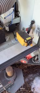
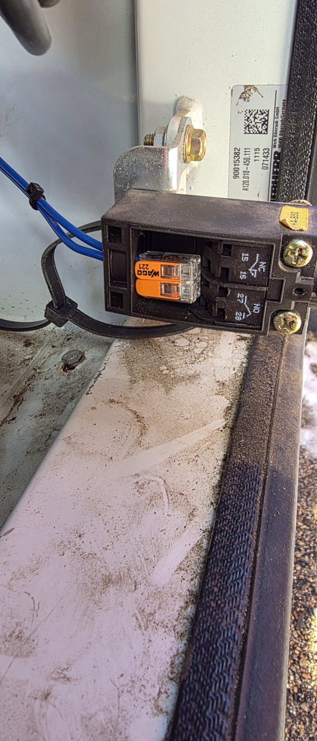
On the Hup cranes we have slewing limit switches. We also have the option slewing encoders and the collector option.
• The limit switches (S610S and S615S) work only when the options are not enabled (angle, Top Zone and collector)
• If the top zone option is enabled we must also enable the angle option. When the 0° angle is enabled, the slewing movement cuts will be made by the encoders (B260N and B261N) and from 0°.
• If the collector option is activated, we bypass the limit switches, so there is no more cutting of the three turns in the slewing
Check the swing motors o make sure that mechanically there was no failure and the brake are physically releasing.
Update crane CCS software and update each drive
BST21-284-B – New CCS version 1.8.21 and updating of the HUP variable frequency drives_EN (2) (1)
**NOTE** This will delete the serial number and load cell and encoders
When teaching in the MR329 it isn’t required to set the 3dead turn parameter if the block will reach the ground before running out of rope on the drum.
If you previously set the 3 dead turn and need to get rid of the saved information on CSS, unpair the hook height encoder, pair it. Turn off CCS and turn it back on. Teach the zero height, and the upper height and then escape out of the teach in menu. A prompt will warn you on startup that 3 dead turns has not been set.
This is important because if you have a crane that reaches below the base of the crane the 3 dead turn function may preclude you from going low enough.
You can get around this if you want by pulling out rope onto the ground and setting the 3 dead turns but it may screw you on the next jobsite.
1917.46(a)(1)(ii)
The accuracy of the load indicating device, weight-moment device, or overload protection device shall be such that any indicated load (or limit), including the sum of actual weight hoisted and additional equipment or “add ons” such as slings, sensors, blocks, etc., is within the range between 95 percent (5 percent underload) and 110 percent (10 percent overload) of the actual true total load. Such accuracy shall be required over the range of daily operating variables reasonably anticipated under the conditions of use.
While filling the washer bottle, all the fluid would leak out.
On the output side of each washer pump is a check valve.
 to access the valves the A/C unit must be removed.
found that the check valves were broken and cracked, presumably from freezing. Replaced the valves ( toyota part # 85321-26020) and washer bottle stays filled.