The GR plug is for the auto greaser option. The auto greaser does not have GR marked on the plug. If the GR plug is not plugged in the slew ring will not be automatically lubricated.


Rocky Mountain Crane Service Logs
The GR plug is for the auto greaser option. The auto greaser does not have GR marked on the plug. If the GR plug is not plugged in the slew ring will not be automatically lubricated.
This is only for the Upper and Lower hoist limits and the Inner and Outer Trolley Limits
—– Limit calibration —–
With machine in work,
press the radio control buttons A and D simultaneously for at least 5s until the radio control buzzer sounds.
At this point the machine goes into calibration mode and the radio control screen changes showing the current maximum and minimum limits.
It is possible to move the lifting and trolley axes WITHOUT LIMITATION to bring them manually to the maximum and minimum positions.
Once the limit position has been reached, by keeping the corresponding button pressed for at least 3s, the quota (minimum or maximum) will be fixed to the current position of the axis
and to the value displayed by radio control.
The keys are assigned as follows:
– key A for minimum lifting limit (LOWER LIMIT CLOSEST TO GROUD)
– key B for maximum lifting limit (UPPER LIMIT CLOSEST TO JIB)
– C key for minimum cart limit (INNER TROLLEY LIMIT)
– D key for maximum cart limit (OUTER TROLLEY LIMIT)
The LEDs positioned above the keys indicate whether the limits calibration has been carried out (LED on steadily) or not (LED off), respectively at the minimum and maximum lifting and trolley levels.
——————-
Shunt code for Topsite shunt when activated is 8528
This code can be any code you choose, in an attempt to standardize the shunt code please make it 8528 at the time of setup.
Currently the shunt code for the MDT389 SN: 627012 is 1025
Minutes Hour and Minutes+Hour
If it is 10:30 in the morning, it would be:
301040
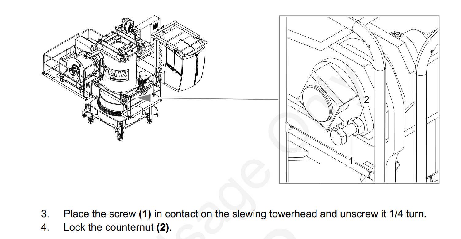
There are 4 pins that connect the tower head to the turntable. Near these pins there are 4 bolts that apply torsional pressure against the pins. The Operator Manual says to tighten the bolts then back them off 1/4 turn and set the jam nut. Blake Smith from Potain recommends these bolt be tightened and not backed off. Throughout operation of the crane occasionally re-tighten these bolts. The pin connections will pop as has they “seat in” during operation and will eventually quiet. This is a common issue with new 389 cranes.
Was trying to tower up and let Jib retaining rope out. Toggle on my remote was to the right on mast. Hydraulic motor would not come on and wasn’t able to let out the Jib retaining rope. Breaker Q940M was not tripped. Looked at my Erection aid and where S916S & S918S was just —- Which it should have been reading S916S. Switches were good, checked B911N (Inductive control detector of retaining winch) will also put —- if it’s not reading correctly. Had 48V at G27. K916A was not Acted on. Had 48V at K916A. Wiggled contactor and orange plunger on K916A was Acted on. Erection Aid was reading S916S. Hydraulic motor and Jib retaining rope started working. Need to probably replace K916A
Operator gave hoist up command, Brake release felt sudden and hard, Followed by a very slow hoisting up or down. Some cases the crane would kick the operator out shortly after the hoist function was given. When the crane faulted E.65 was displayed on the KEB hoist drive.
New Encoder was ordered
Hoist drive was placed in to Degraded Mode 
Replaced hoist Encoder, 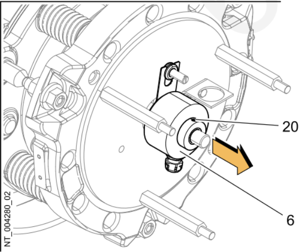
Took hoist drive out of degraded mode and normal operation resumed.
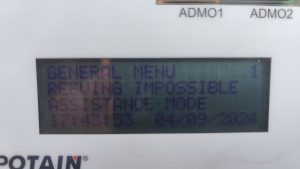
Processor shows the following
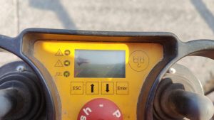
Remote shows the following
Crane may think it is in “High Height” (H3) and 4 parts of line are selected (DM). In H3 (High Height) crane must be operated in 2 parts of line (SM), not enough line on hoist drum.
Make sure S917S is adjusted properly. It is the limit box on the end of the jib retaining motor.
If the switch is adjusted properly, and not activated (Normally Closed NC), check Fault Stack (3-4-1)
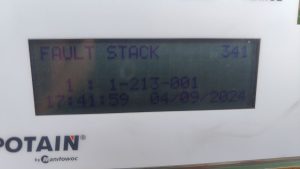
Most recent fault is that the CanOpen Module is not detected. Verify by checking Can Module Inputs on processor (3-9-1)
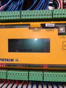
Check for RUN light on Can Module (U213X)
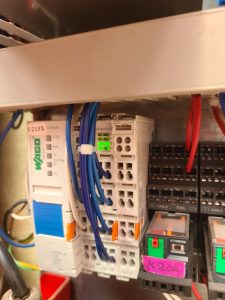
If the RUN light is not on check T131F (the +24VDC transformer) for power. If the DC OK light is not on, the transformer is not working.
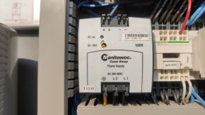
Check Circuit Breaker Q133F to make sure transformer is being supplied 480 VAC. If breaker is tripped and cannot be reset, replace transformer.
If RUN light on, but flashing, it is not communicating with the processor. It will still show U213X as not detected. Disconnect H4, H5, H6 connectors on Can Hub (U237X)
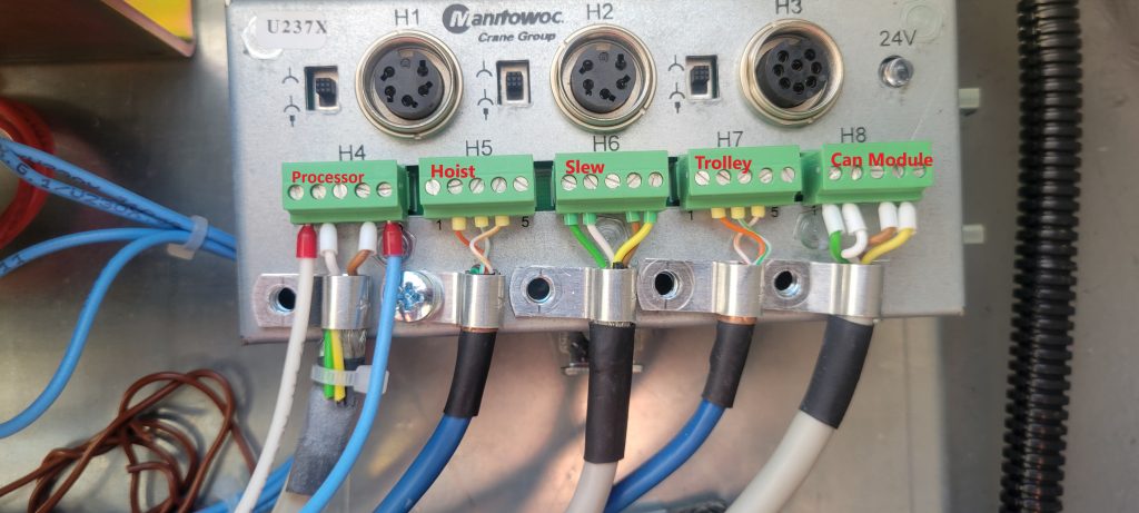
These are the communication cables for the labeled drives and operate on the same CAN2 network. If the H3 disappears (may need to restart crane), plug each cable back in to determine which one (or more) may be the problem. The cable(s) may not be the only problem. It quit possibly could be the drive(s) as well.