Rocky Mountain Crane Service Logs
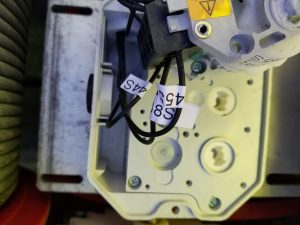
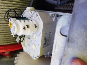
Proper identification of height sensor on telescoping drum
H1 Full working height
H0 Lower working height
HT Lowered for transport
The crane probably thinks it is luffed. Check the erection aid menu, and adjust the 2 sensors at the top of the mast (cat head) as needed.
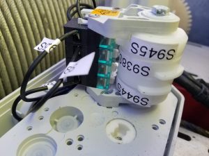
Installed a new memory stick in the swing drive on Igo T85A. Had to go to menu 74 and then to 11 to set the Supply Voltage to get started.
Then had to restart the drive and it went through a motor ID and run ID test. Once complete, had to restart the drive again and it worked fine. The drive said it was ready to work, but was unresponsive. Make sure to restart again.
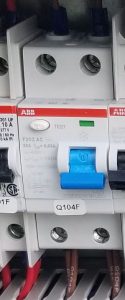
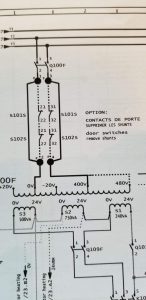
Customer complained that the AC power in the cab was not working. When asked, the customer still had lighting, but the AC plug ins were not working. Found that the circuit breaker Q104F was tripped.
**note** when circuit breaker was tripped the indicator was green. When it is working, the indicator is red
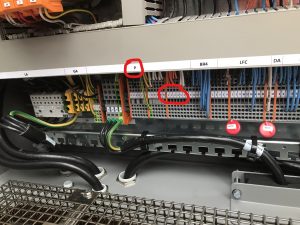
These are 480 volt wires! Insure all power to crane is shut off!
Jumper P strip 1 to 2 and 3 to 4 (all should have continuity)
When replacing the radio remote receiver on HUP, had to go into CCS and enter address and group of transmitter (radio remote).
When you turn on the remote, the screen stays on the page showing group and address. Go to Mounting>Configuration>Radio Control (6-2-6) and enter both group and address. Once complete press ENTER and look for the check mark. ESC, ESC, ESC and press start button
Here are the instructions for derating the moment and max thresholds