Have to clear active faults on CCS. Go to Teach and Program to enter code. Press ESC once and go to Maintenance. Press ENTER twice for each fault displayed.
Wire Rope Replacement
ALWAYS pull wire ropes by hand when replacing. Especially for the initial reeving.
Potain Igo T85A (27148) – Weathervane light does not come on
Even though the actuator weathervanes the crane, the light does not come on. There is a microswitch on the back of the slew motor. Proper adjust by the manual would require removing the slew motor. For a field fix, remove the cover (see previous post for proper removal). With the cover removed, take crane out of weathervane (slew brake set). There is an adjustable plate that contacts the microswitch when activated. Loosen the screw with a 8mm wrench and pull the contact plate up towards the microswitch. Tighten slightly more than finger tight. Activate the weathervane and verify the light comes on. If it comes on, take the crane out of weathervane and tighten completely. Replace cover as outlined in the previous post.
Potain Hup 40-30 (22131) – Does not allow for validation for mast locks
When towering up, mast locks are extended but the orange validation button does not appear. S934S does not close. Jumper 24 VDC to G5 and horn honks and validation button appears. Mast lock switches should look like this (folio 11):
Mast locks extended:
S933S 0 (open)
S934S 1 (closed
Mast locks retracted:
S933S 1(closed)
S934S 0 (open)
Will update once crane is down and switches are tested
Potain Igo T85A (27148) – Greaser not working
Amber light on the control panel with grease symbol on, but grease reservoir full.
Light comes on when it’s working, and when grease level is low. Grease pump motor is 24 volts DC. Found 8 volts. Removed 3 pump bolts and water poured out. Circuit board was shorted. Replace assembly.
(Note. K600M must be engaged to activate greaser circuit.)
Potain 27148 (Igo T85A) shuts down after 2nd Speed
Operator complaining that the crane is kicking off when hoisting. Determined it is only in 3rd speed. Hoist speed sensor needs to be adjusted and the end of shaft needs to be cleaned of debris.
Boosting Antenna Signal on Autec Receiver
According to Ken (716-220-5153) only do this when adding the “long” antenna or you could damage the receiver (yellow box).
“S1” is trolley out first speed
“S2” is trolley in first speed
DIP switch #1 & #2
-Main power off, remove 4 screws on transmitter. Find DIP switch #2 and move it to its opposite position.
-Main power on, and remote on press start button. Crane should start up, but not honk
-Hold the start button, function button (black button on opposite side of start button) and S1 (trolley out first speed)
-This enters you into the service menu and toggle through the menu using S2 (trolley in first speed) until you reach RF Power (should read normal)
-S1 until the the RF Power says “MAX” (it goes normal, high and max)
-Press start button, function button and S2 and it read Result OK when complete.
-Shut off main power, switch DIP switch #2 to original position and replace cover
Autec Remote loses trolley and hoist functions
Customer says lost trolley and hoist functions (in/out & up/down). Told to switch to push button remote and all works.
Remove cover and check fuses under black caps (5)
Potain T85 Remote not connecting to crane
At start up, remote does not connect to crane. K320 relay (horn relay) just clicks.
Remove J12/5 24VDC yellow wire from U230X
Remove A1 24VDC Pink and Grey wires from K100A
Jumper J12/5 to A1
Restart Crane
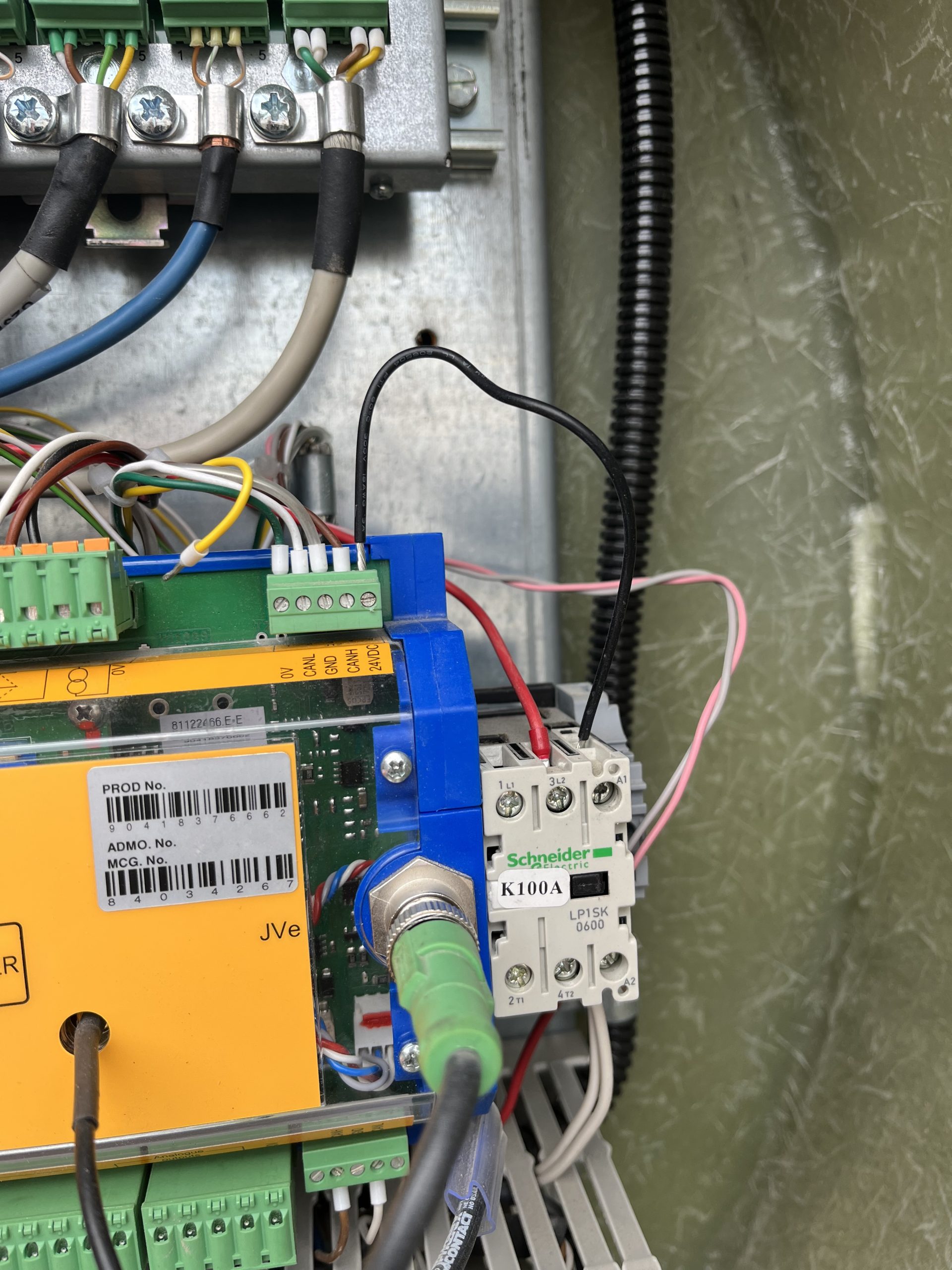
This takes the KK plug and its connections out of the circuit.