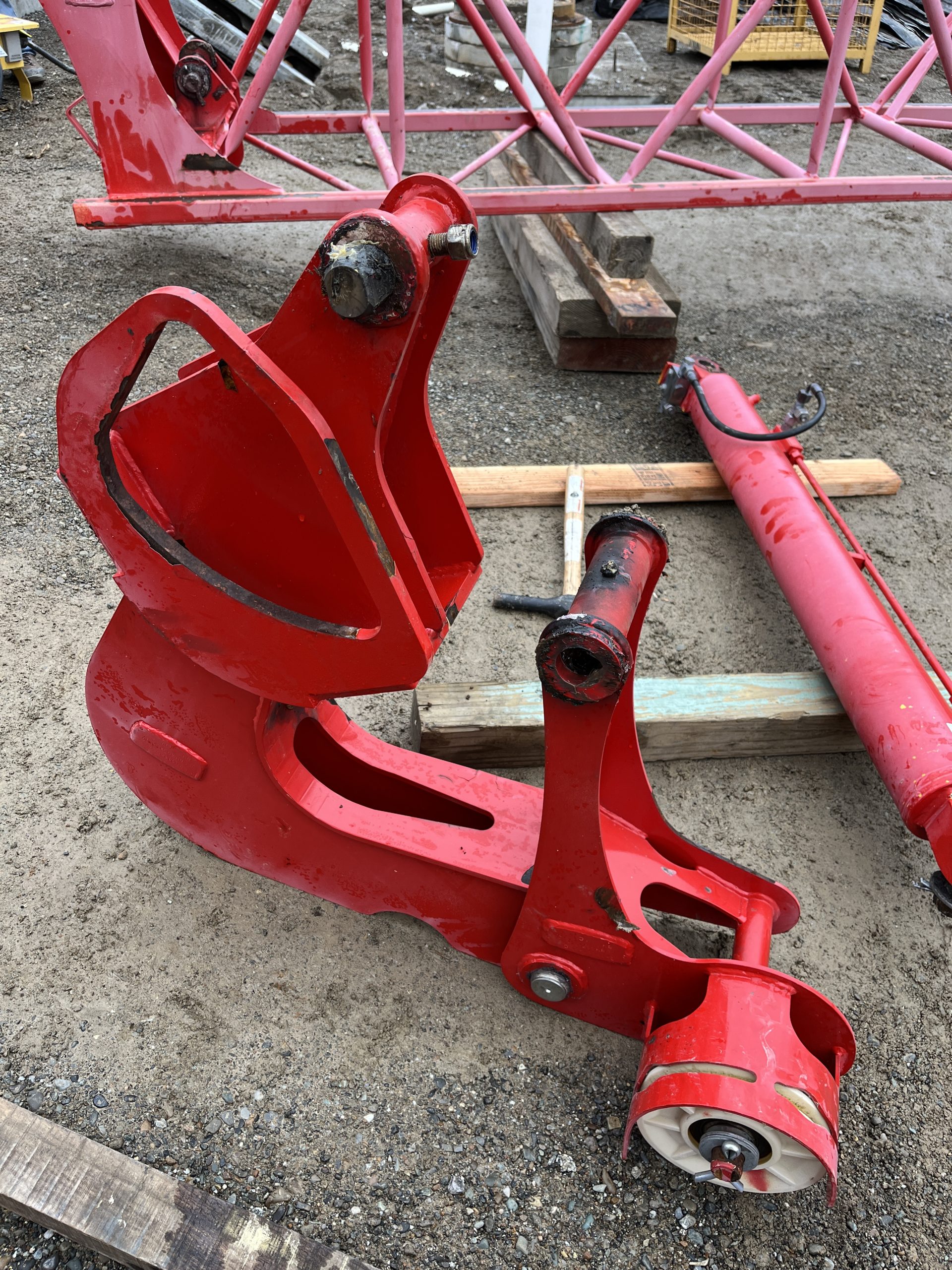
After you bring the crane into maintenance mode and get it in the position to start taking the Hydraulic cylinder, jib attachments, and jib off. The operator manual disassembly instructions do not match the actual process to remove the outer jib.
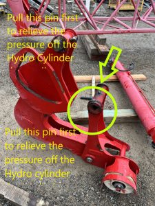
With the pictures above the picture from the manual tells you to pull this pin to get the cylinder off. Which there is to much pressure on the cylinder to get that pin out with out possibly bending the Jib on the crane. When you get to this step of taking the Hydraulic Cylinder off you will want to revert to the edited picture above and pull that pin first.
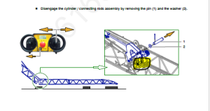
The operator manual disassembly instructions do not match the actual process to remove the outer jib. When removing the outer connecting rod/hydraulic assembly, there is no need to remove the pulley pin and roller assembly as detailed in this step.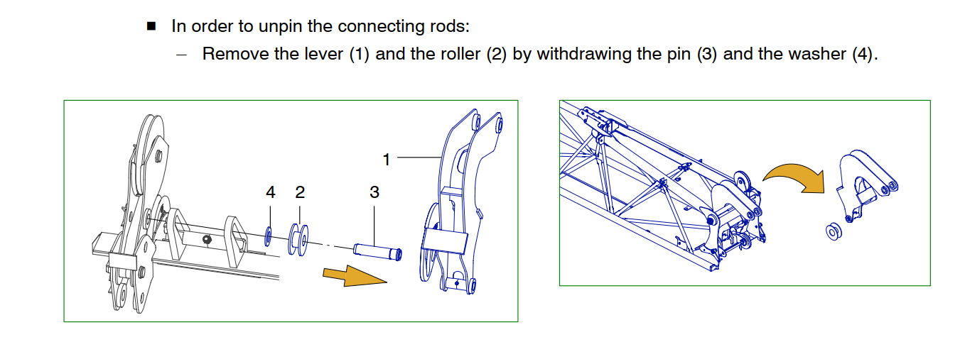
The connecting rod (4)(image below) pivots on a special pin with a through bolt. To remove the connecting rod (4) Remove the through bolt, slide out of the connecting rod pin (4) The sheave assembly that is detailed in the image below (1) is separate and will unpin without any interference from the Connecting rod (4)
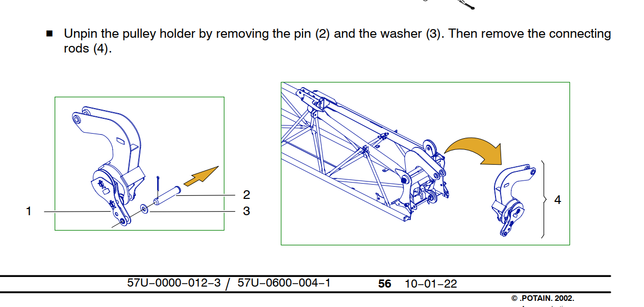
The connecting rod pin fits into a slotted rail, the pin needs to be at the bottom of the rail and turned 1/4 turn to be removed. (Note the trolley cable sheave is installed and pined into place. The pin required to pin the sheave is the same pin used to hold the pulley holder (1) in place. There is some paint in the I.D. of the holes, it is recommended to install the pin first with anti-seize to help drive out the paint before installing the sheave. )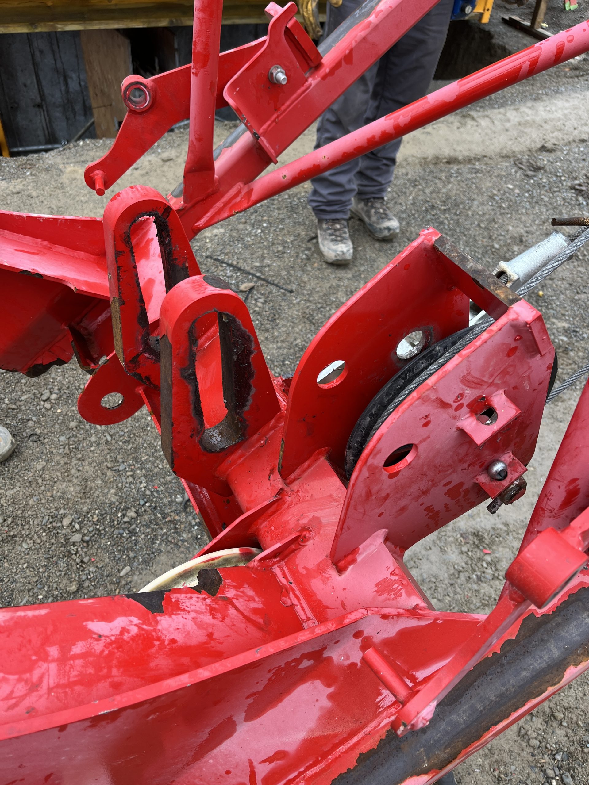
The connecting rod assembly can be removed without completely disassembling the assembly as detailed in the instructions.