Every HDT 80 with a serial number that starts with a 400 number has a override option. If you overload your crane and you can’t hoist up or down because you overloaded the crane hold the start button down while hoisting down.
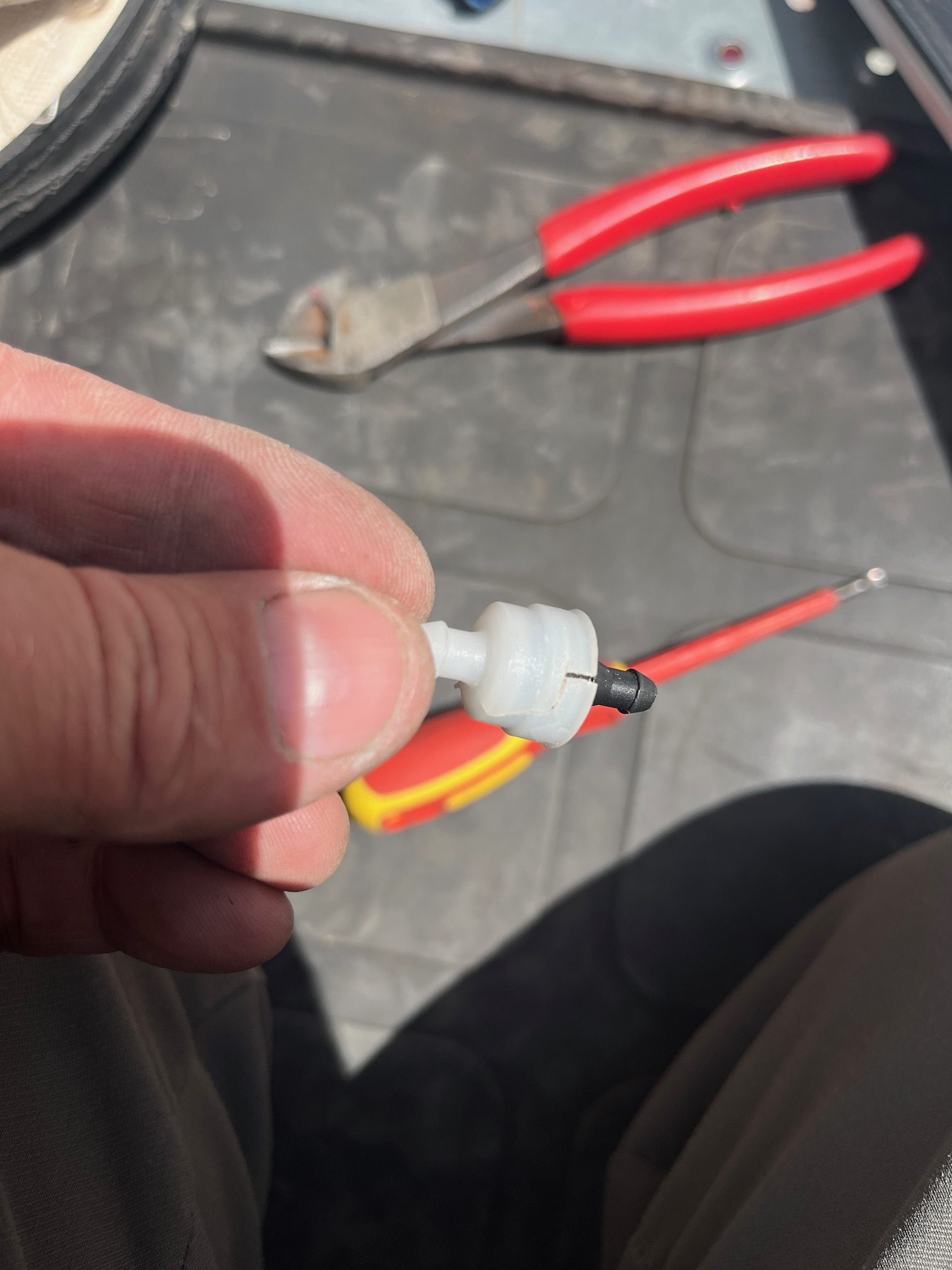
Windshield washer check valves
While filling the washer bottle, all the fluid would leak out.
On the output side of each washer pump is a check valve.
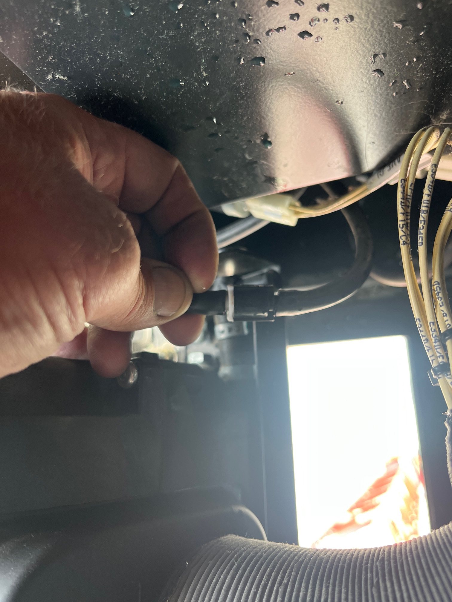 to access the valves the A/C unit must be removed.
found that the check valves were broken and cracked, presumably from freezing. Replaced the valves ( toyota part # 85321-26020) and washer bottle stays filled.
HDT 80 hoist line for erection and dismantle
HDT 80 When erecting or dismantle make sure you have slack in your hoist line while folding the jib. It does not have auto winding on the hoist drum so it can get supper tight and there is no limits to stop it. click on the link to see in the manual where you need to make sure you have slack in your cable. It is best to have about 10 ft of slack in your cable.
HDT 80 limit switches
While erection and dismantle there is no limit switches that will stop you. Also there is no 125 limit for your hoist so you do not want to get your hoist rope tight at all or you will be bending and breaking stuff.
Top Site & Pairing New slewing encoders on HUP
When setting up top site on a hup or pairing new slewing encoders there is a few more steps that you need to take that doesn’t explain in the manual. I have added some key notes in the top site chapter in the manual to get the job done. top site manual
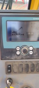
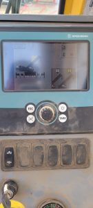
Grove RT890E LMI Screens
Here are the screenshots, should the display fail


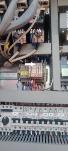
FM Gru 1589 Relay Explanation
Rundown of relay to contactor logic

Contactor 34K1 controls valve bank coils.
Y1 Mast down
Y2 Mast up
Y3 Jib up
Y4 Jib down
Relay bank

36K1-5 relays
36K1 Mast down (34K1-Y1)
36K2 Mast up (34K1-Y2)
36K3 Jib up (34K1-Y3)
36K4 Jib down (34K1-Y4)
36K5 Control relay (supply)
FM Gru 1589 will not raise the jib in erection mode
Tried to erect 1589 and the jib would not raise. Checked hydraulic pump, and it was building pressure, but the coil to open the valve bank was not being activated.
Contactor was switching to open, but the control relay for the valve was bad.
Light would turn on the face of the relay, but would not actually switch. The orange screw could be turned to manually make the switch and the jib would go up. Replace relay.
GR Plug – MDT 389
The GR plug is for the auto greaser option. The auto greaser does not have GR marked on the plug. If the GR plug is not plugged in the slew ring will not be automatically lubricated.


FM GRU 1589 Limits Hoist and Trolley
This is only for the Upper and Lower hoist limits and the Inner and Outer Trolley Limits
—– Limit calibration —–
With machine in work,
press the radio control buttons A and D simultaneously for at least 5s until the radio control buzzer sounds.
At this point the machine goes into calibration mode and the radio control screen changes showing the current maximum and minimum limits.
It is possible to move the lifting and trolley axes WITHOUT LIMITATION to bring them manually to the maximum and minimum positions.
Once the limit position has been reached, by keeping the corresponding button pressed for at least 3s, the quota (minimum or maximum) will be fixed to the current position of the axis
and to the value displayed by radio control.
The keys are assigned as follows:
– key A for minimum lifting limit (LOWER LIMIT CLOSEST TO GROUD)
– key B for maximum lifting limit (UPPER LIMIT CLOSEST TO JIB)
– C key for minimum cart limit (INNER TROLLEY LIMIT)
– D key for maximum cart limit (OUTER TROLLEY LIMIT)
The LEDs positioned above the keys indicate whether the limits calibration has been carried out (LED on steadily) or not (LED off), respectively at the minimum and maximum lifting and trolley levels.
——————-